
| SPS stands for Spatial PCM Sampling, and is a modern alternative to Ambisonics for recording, synthesizing, manipulating, transmitting and rendering of spatial audio contents. This page provides the definition of the SPS concept, show similarities and differences with Ambisonics, and presents the hardware and software tools employed for working with SPS signals having various numbers of channels. Finally, the first real world application of the SPS approach is presented, the Mach1 8-channels soundtrack currently supported by the Samsung VR portal and by the New York Times VR app
|
Ambisonics is a widely employed format for capturing, transmitting and decoding spatial audio, using 4, 9, 16, 25, 36 channels or even more (High Order Ambisonics, HOA). It was invented in the seventies by Michael Gerzon and colleagues, and has a long history of successes (few) and failures (many). In Ambisonics, the spatial information is obtained representing the sound field as a multichannel track, in which each channel corresponds with a virtual microphone having a very complex polar pattern, mathematically described by the corresponding Spherical Harmonics function.
SPS is a modern audio format providing all the same capabilities of recording, synthesizing, processing, transmitting and decoding as Ambisonics, adding some inherent advantages which will be explained here.
SPS was invented by Alberto Amendola and Angelo Farina, during acoustical measurements performed inside the Grand Théâtre de Provence, Aix en Provence, on 19 June 2007. In that case, for mapping the sound reflections inside the theatre, Alberto Amendola suggested to use a Sennheiser shotgun microphone, mounted on an automatic two-axes turntable, for sampling the sound arriving by hundredths of directions while measuring room impulse responses.

So the first implementation of SPS was with room impulse
responses, measured one after the other: each one was the response of a very
directive microphone pointing in one of hundreths of directions, covering almost
uniformly the whole sphere.
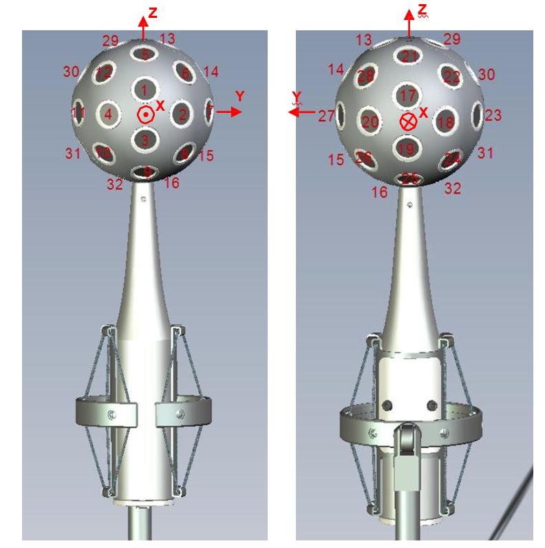
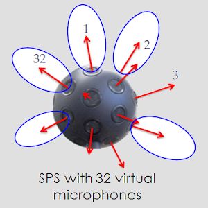
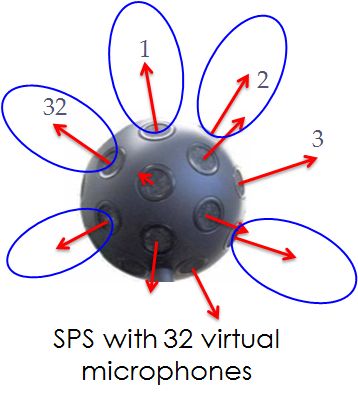
In 2010 we did buy our first Eigenmike, and this allowed to record SPS signals
simultaneoulsy with 32 ultradirective virtual microphones, pointing in the same
directions of the capsules of the Eigenmike:
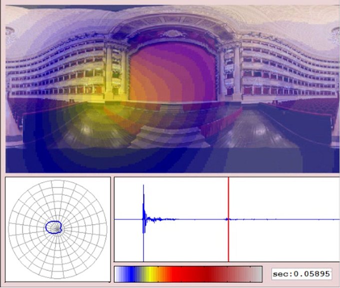
Thanks to these realtime capabilities, SPS-32 was first used as a tool for creating colour maps of the spatial distribution of sound, employed both in concert halls and inside cars, as it was published in these papers:
|
Marco
Binelli, Andrea Venturi, Alberto Amendola, Angelo Farina |
130th AES
Conference, London, 13-16 May 2011 |
|
|
Angelo
Farina, Alberto Amendola, Andrea Capra, Christian Varani |
Spatial analysis of room impulse
responses captured with a 32-capsules microphone array |
130th AES
Conference, London, 13-16 May 2011 |
|
Angelo Farina, Lamberto Tronchin |
3D Sound
Characterisation in Theatres Employing Microphone Arrays |
Acta Acustica
united with Acustica, vol. 99, n.1, pp. 118-125, ISSN 1610-1928,
January/February 2013 |
Here a frame captured from the video rendering software written by Alberto Amendola for realtime mapping of room reflections inside the La Scala theater:
The usage of SPS as an alternative to Ambisonics for recording and playback was also explored successfully, as reported in the following papers:
An Ambisonics multichannel sound track is not based on the concept of "position of the loudspeakers", as in a stereo (Left-Right) or "surround 5.1" (Left, Right, Center, Sub, Left Surround, Right Surround) formats.
Instead, the complete spatial information is represented by a number of "spherical harmonics" signals, at increasing orders. The number of signals for each order is increasing, and the corresponding polar patterns of the equivalent "virtual microphones" are shown here:
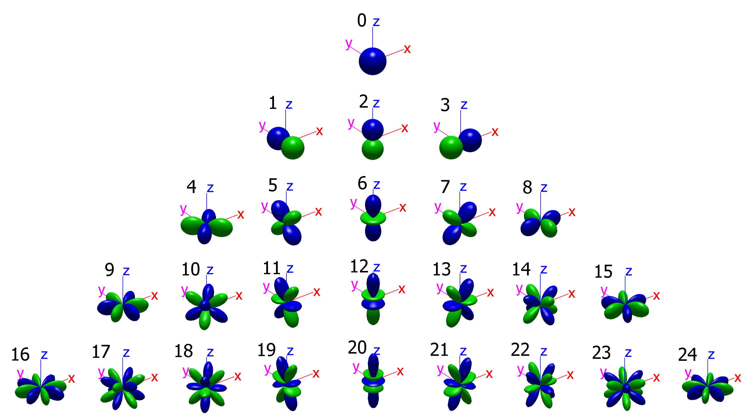
An Ambisonics stream is said to be "of order n" when it contains all the signal of orders 0 to n. For example, an Ambisonics signal of order 3 (the most widely used, nowadays) contains 16 channels: 1 of order 0, 3 of order 1, 5 of order 2 and 7 of order 3. Please note that, following the Ambix convention, numbering of Ambisonics channels starts from 0 instead of 1.
An SPS multichannel track consists in bunch of signals recorded by a set of coincident directive microphones, pointing all around, covering (almost) uniformly the surface of a sphere. As the microphones are coincident, the SPS signals do not contain time differences between the channels, only amplitude is different, depending on the position of the sound source. In this, SPS is exactly as Ambisonics, coding the spatial information based only on amplitude and not on phase. However, in SPS there are never "reversed polarity" signals, as the virtual microphones being employed are cardioids of various order, whithout any rear lobe with reversed polarity.
The number of channels can be chosen among the known regular polyedrons (Platonic solids), up to 20 channels. Above 20 it is necessary to use not-exactly-uniform geometries (Archimedean solids), such as the truncated icosahedron (the Eigenmike). The most common number of channels, and the corresponding geometries, are listed here:
| Figure | N. channels | Description |
 |
4 | faces of tetrahedron |
 |
6 | faces of a cube |
 |
8 | faces of an octahedron |
 |
12 | faces of a dodechaedron |
 |
20 | faces of an icosahedron |
 |
32 | faces of a truncated icosahedron |
 |
62 | faces of a rhombicosidodecahedron |
 |
92 | faces of a snub dodecahedron |
There is not yet a standard absolute orientation and a standard channel ordering for all of these geometries, except for the tetrahedron, for the octahedron (SPS-8, aka Mach1, described later), for the dodoecahedron (SPS-12) and for the truncated icosahedron (SPS-32, which employs the same geometry as the capsules of the Eigenmike), as shown here:
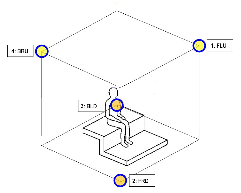 |
Tetrahedron
|
||||||||||||||||||||||||||||||||||||||||||||||||||||||||||||||||||||||||||||||||||||||||||||||||||||||||||||||||||||||||||||||||||||
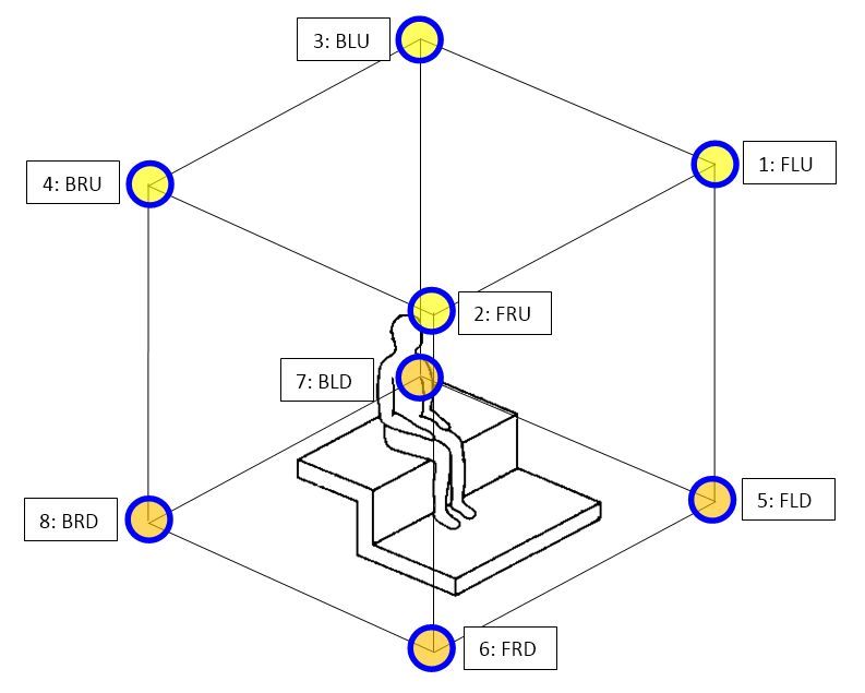 |
Octahedron (Mach1)
|
||||||||||||||||||||||||||||||||||||||||||||||||||||||||||||||||||||||||||||||||||||||||||||||||||||||||||||||||||||||||||||||||||||
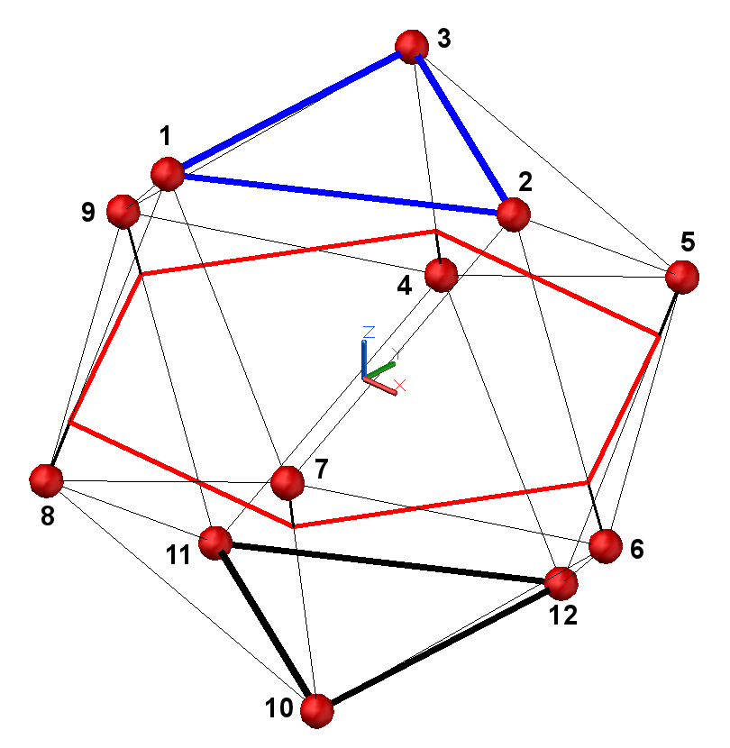 |
Dodecahedron (12 directions at the vertexes of an icosahedron)
|
||||||||||||||||||||||||||||||||||||||||||||||||||||||||||||||||||||||||||||||||||||||||||||||||||||||||||||||||||||||||||||||||||||
|
SPS-32 (Eigenmike)
|
Truncated Icosahedron
|
Please note that, in the tables above, azimuth and elevation coordinates are conforming to current ISO2631 standard, as shown here:
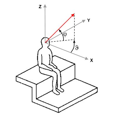
Be aware that some software is not compliant
with ISO standards, for example Ambix plugins and Facebook Spatial Workstation,
which employ azimuth with reversed polarity. Eigenstudio instead has correct
azimuth, but uses an elevation counting "down" from 0 at North pole, 90 at Equator and
180 at South pole.
The relationship between SPS and Ambisonics is substantially the same relationship occurring, for time domain waveforms, between a standard PCM waveform and its Fourier spectrum.
A time domain continuous (analog) waveform, can be represnted digitally by a sequence of pulses (PCM Pulse Code Modulation) as shown here:
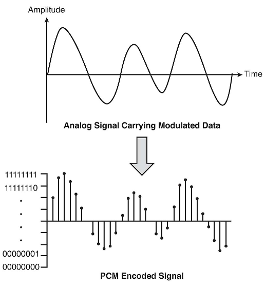
Each pulse is also called a "Dirac's Delta Function".
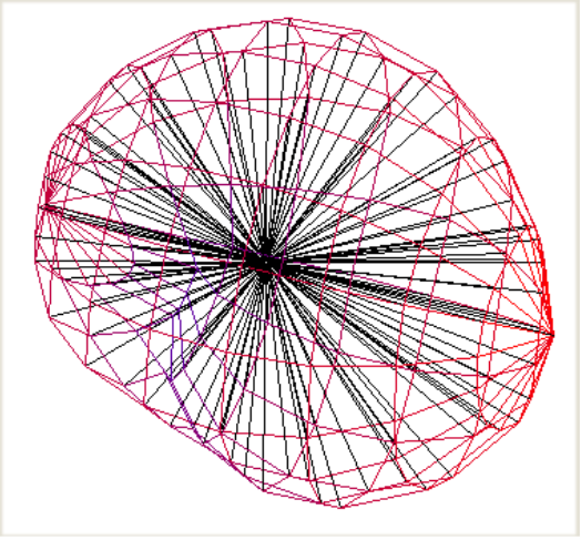
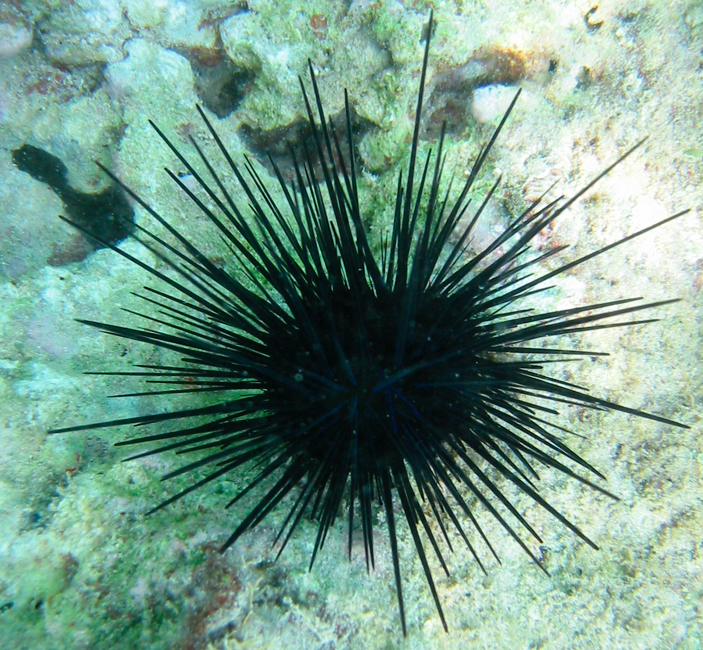
In space, a "balloon" expressing the amplitude of sound arriving form every direction can also be approximated by a spherical distribution of "spatial pulses" or "spatial Dirac's Delta Functions", which can be seen as the spikes of a sea urchin:
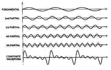
Coming back to a waveform in time domain, we can also represent it as the summation of a number of sinusoids and cosinusoids with increasing frequency, each with proper amplitude (the amplitudes are given us by the Fourier transform):
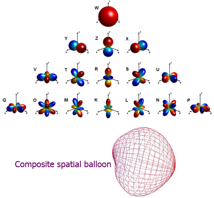
Similarly, a spatial balloon can also be represented as the summation of a number of spherical harmonics functions of increasing spatial frequency ("order" in Ambisonics terminology), each with proper amplitudes (the amplitudes are given use by the Ambisonics encoding formulas, or by the A-format to B-format filtering):
In conclusion, it can be said that both SPS
and Ambisonics are intermediate formats capable of decomposing a complete
three-dimensional sound field in a number of discrete components. These are just
Dirac's Delta pulses for Spatial PCM Sampling, and instead are complex
oscillating functions ove the surface of a sphere for Ambisonics.
But conceptually both are just projections of the original data set over
different kernels of base spatial functions, and the complete workflow going
from recording to playback is exactly the same:
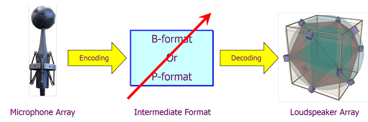
The red arrow means that the intermediate format (called B-format for Ambisonics, P-format for SPS) can be easily manipulated, although some sort of manipulations are easier in one of the two formats, and more tricky in the other.
For example, performing rigid rotatons of the
soundfield is trivial in Ambisonics, and tricky with SPS signals. On the other
side, doing "spatial equalization", which means boosting the gain in some
directions and reducing the gain in other directions, is trivial with SPS
signals and very tricky with Ambisonics.
As it is possible to go back and forth from SPS to Ambisonics and vice versa
(exactly as we can go from time domain to frequency domain and back, using FFT
and IFFT processors), the user can choose the intermediate format more suitable
for his needs.
However, in most cases, SPS is advantageous (exactly as a PCM wave is
advantageous over the usage of complex spectra for representing and processing a
sound recording):
first of all, understanding SPS is much easier than understanding Ambisonics
an SPS signal can be created without complex mathematical formulas, just adjusting some gains on a mixer, on the channels corresponding to the directions where you want to place your sound sources
for SPS signals with large channel counts (32 and above) there is no need to "pan" across the channels, you can send each sound source to just one channel, with the exception of the case when you want to "spread" spatially the sound over more directions
for SPS signals with a little number of channels (for example Mach1, 8 channels) panning is required, but it can be done with traditional well known panning functions, such as VBAP at low frequency and VBIP at high frequency.
finally, also for rendering the intermediate format to the final loudspeaker system (real or virtual, in case of headphone listening) the SPS method is quite simple, as each loudspeaker is simply fed with the signal of the SPS components surrounding it. And in the very special case to have one loudspeaker in the exact location of each virtual microphone, then no decoding is necessary, as each loudspeaker is fed with just one channel of the SPS stream. This is the case, for example, of binaural rendering of the Mach1 format, which does not require any decoding.
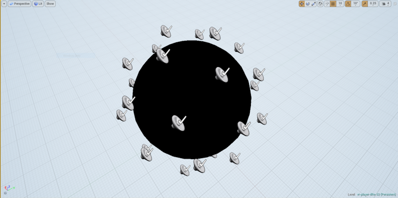
For playback of panoramic video with spatial audio soundtracks over a VR device such as Gear VR, Google Cardboard, HTC Vive, Oculus Rift, etc. the playback software becomes tricky with Ambisonics (as you need an advanced Ambisonics decoder, feeding each virtual loudspeaker with a complex mixture of all the Ambisonics signals), whilst it is really trivial with SPS: it is just necessary to place a spherical distribution of sound sources around the spherical video projection screen, each one fed with one channel of the SPS stream, as shown here for our Unreal Engine player for SPS-32 soundtracks:
Mach1TM is a registered trademark of Mach1studios (http://www.mach1studios.com), a startup company based in New York (US) and founded by Dražen and Jacqueline Bošnjak; Dylan Marcus is Mach1's Technical Director. These guys were the first to create the tools necessary for employing SPS signals in the field of "VR videos", developing software both for generating Mach1 spatial audio soundtracks and for rendering them on Head-Mounted Displays, in particular on the Samsung Gear VR platform.
A Mach1 multichannel track corresponds to SPS-8, where the 8 virtual microphones are pointing at the vertexes of a cube, as shown earlier on this page.
Mach1 is becoming widely accepted as one of the best
"spatial audio" formats accompanying 360-degrees videos on VR head-mounted
displays. A "spatial audio" sound track ensures that users of these head-mounted
displays equipped with headphones hear a binaural rendering of the spatial
scene, which maintains the absolute position of the sound sources unchanged,
independently on the direction where the user is looking.
Currently 4 "spatial audio" formats are available for different VR platforms and
software:
| Name | N. channels | Platform | Software |
| Ambix (1st order Ambisonics, FOA) | 4 | Cardboard, Daydream, Gear VR, Gear VR, Oculus Rift, HTC Vive, Samsung Odyssey, Oculus Go,
Oculus Quest (untethered) |
Youtube, Facebook 360, Jump Inspector, DeoVR, Vive Cinema |
| TBE (almost 2nd order Ambisonics) | 8+2 | Gear VR, Oculus Rift, HTC Vive, Samsung Odyssey, Oculus Go,
Oculus Quest (untethered) |
Facebook 360, Oculus Video, EccoVR, Vive Cinema, DeoVR |
| Ambix (3rd order Ambisonics, TOA) | 16 | Cardboard, Oculus Rift, HTC Vive, Samsung
Odyssey, Oculus Quest (tethered) |
Jump Inspector (discontinued), Vive Cinema |
| Mach1 (SPS) | 8 | Gear VR, Cardboard, Daydream, Oculus Go, Oculus
Quest (untethered) |
Samsung VR, New York Times VR |
For most people, "spatial audio" means 1st order Ambisonics, but this is definitely the worst of the 4 available formats, providing a spatial resolution which is not enough for providing good realism. On the other hand, TOA (Third Order Ambisonics) produces significantly better results, but working with TOA signals requires knowledge and expertise, and most producers of 360 videos simply do not have knowledge, nor time to learn how to master TOA, nor even higher orders (Ambix software goes up to 7th order, which means 64 channels...).
Furthermore, 3rd order Ambisonics requires 16 channels of uncompressed PCM audio, something which is not graceful for videos to be streamed live. In practice, these 3rd-order recordings need to be downloaded first, then sideloaded on the HMD for being watched with Jump Inspector. Currently no VR portal allows for streaming videos with 3rd order Ambisonics soundtrack.
Facebook did a great effort releasing easy-to-use software tools for their proprietary TBE format, but in the hurry of releasing them, they incurred in a severe bug regarding encoding of elevation of the sound source, resulting in a completely distorted soundscape. This error has now been fixed (as of 20 August 2017), and so, finally, Facebook's TBE format becomes a good option for delivering spatial audio soundtracks with decent spatial resolution and good quality. This format has the additional advantage of making it possible to add two not-spatial channels, which remain "head locked" and can be useful for comments or not-diegetic audio information.
But now we have finally a competitive alternative to
TBE: Mach1. Understanding SPS is much easier than understanding
Ambisonics, and standard production techniques can be used for panning sounds in
the SPS format: you just need to know "where" in space each virtual microphone
is pointing to. The information presented above provides this knowledge, so synthetic Mach1
soundtracks can be created with a normal mixer. And the 8-channels stream can be
easily compressed with AAC or other efficient codecs, making it possible to use
it for realtime video streaming.
There are cases, indeed, where the "spatial audio" soundtrack was already
captured or created in another format, possibly at higher spatial resolution,
such as SPS-32, as raw 32 capsule signals form an Eigenmike, as a Third Order
Ambisonics (TOA) with 16 channels, or as TBE 8-channels.
The following chapters explain how to transcode from these formats to Mach1, and
vice versa.
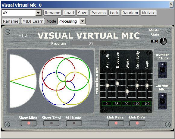
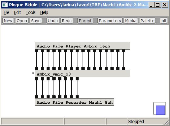
We start from the most basic case, a 1st order Ambisonics (4 channels) stream ready for Youtube. In this case, we generate 8 virtual cardioid microphones employing the Visual Virtual Mic plugin, as shown here:
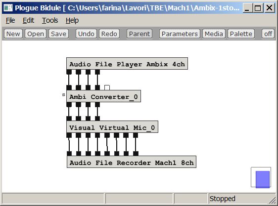
It must be noted that the Ambi Converter plugin was
required, as the recording was in Ambix format, whilst Visual Virtual Mic is an
old plugin, still using the obsolete Furse-Malham (FuMa) format. Hence a
conversion plugin is required for trasforming the modern Ambix signal in the old
FuMa signal, before feeding the Visual Virtual Mic plugin.
This is making use of the maximum number of possible virtual microphones (8)
which have been aimed at the vertexes of the cube, according to Mach1
requirements.
It must be clear that a 1st-order Ambisonics stream does not possess all the
spatial resolution available with the Mach1 SPS format, hence the sound scene
will still remain "smeared" and badly focused, exactly as the original
1st-order Ambix
soundtrack.
However, it is possible to get more sharp virtual microphones, with better
channel separation, if instead of the Visual Virtual Mic plugin we employ the
Harpex-X plugin:
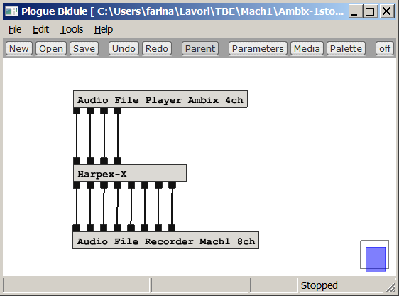
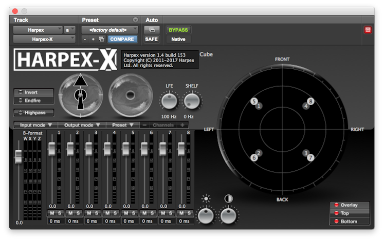
The only problem is that Harpex-X is not free, and quite expensive.
Even better results can be obtained if, instead of starting with just a mere 1st order Ambisonics recording, we have a full third-order Ambisonics recording, which means 16 channels. In this case we can make good use of the additional spatial resolution available in the Mach1 format. The processing in this case requires a third-order Ambisonics plugin for creating the 8 virtual microphone signals, as shown here:
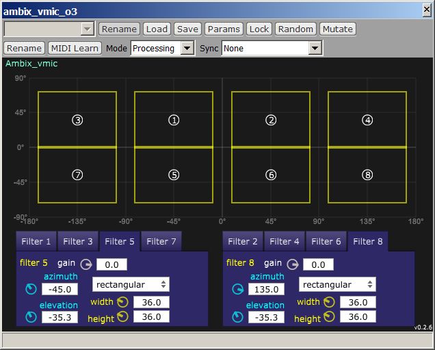
The Ambix Vmic plugin allows for creating virtual
microphones with "rectangular" cross-section, hence making it possible to split
the acoustical scene in 8 "pyramidal" beams, which cover almost perfectly the
sphere, without overlaps or uncovered regions. It is also possible to control
the horizontal and vertical beamwidth of the virtual microphones, providing a
tradeoff between sharpness and "speaker detent" effect.
The first experiments done transcoding form TOA to Mach1 show excellent results,
with a resulting spatial resolution which is almost the same, despite
halving the number of channels, and making it possible to store them in highly
compressed AAC soundtracks.
There are cases when a Mach1 soundtrack needs to be converted back to Ambisonics. Of course, if we want to minimize the loss of spatial information, at least a 2nd order Ambisonics stream must be generated (9 channels), but at that point better to go directly to 3rd order, which is much more widely employed than 2nd order. It is obvious that the resulting 3rd order Ambisonics will never have the same spatial resolution as a "native" 3rd order, as it comes from a source which had just 8 channels.
As the 8 Mach1 signals represent sound sources coming from 8 cardinal directions (vertexes of a cube, as shown earlier on this page) it is quite straightforward to employ an Ambisonics-encoding plugin for converting them back to TOA. For example you can use Ambix Encoder or 03A Panner, as shown here below:
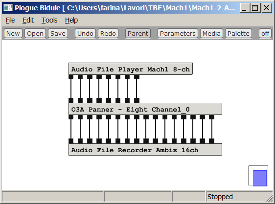
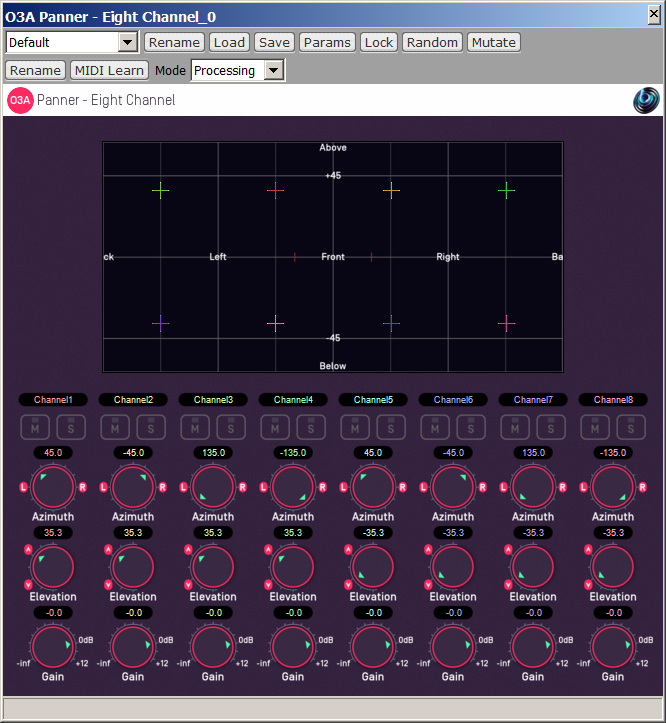
Of course, if one just needs 1st or 2nd order Ambisonics, the same plugin can be employed, recording just the first 4 or 9 channels coming out from it.
And, as usual, if you do not like to install and use these advanced VST plugins, you can always use X-volver with 8 inputs, 16 outputs, with the proper filter matrix called Mach1-to-Ambix-TOA.wav as it will be explained later.
TBE stands for
Two Big Ears, a small Scottish
company which was acquired by Facebook for providing a free
spatial audio platform
for Facebook's 360-degrees "VR" videos.
The TBE format is an 8-channels stream containing a subset of 2nd
order Ambisonics signals, by dropping one of the 9 channels (R) and reorganizing
and rescaling the others, as explained in details
here.
Albeit Facebook's 360-degrees videos with TBE sptial audio soundtrack can be enjoyed only on a small installed base of Samsung Gear VR devices, and hopefully shortly on Oculus Rift devices, the format quickly gained popularity as the sptial resolution provided by its almost-2nd-order Ambisonics, with two additional available channels for "head locked" stereo signals, provides much better results than the currently-dominant Youtube platform with its limited-resolution First Order Ambisonics (4 channels only).
This is due also to the fact that, while on Youtube watching a 360-degrees videos with spatial audio using a browser on a compuer results in a plain stereo mixdown of the signals, instead on Facebook good binaural rendering is provided also for people watching the video on their PC.
Furthermore, for people using HMDs, the Gear VR platform ensures excellent video rendering and high quality headphone listening, at a quality level far superior to Youtube "Google Cardboard" devices. This means that, for a content producer which does not want to release his video and audio streams with reduced quality, the Facebook platform is currently the preferred choice.
But now we have an alternative, thanks to the Samsung VR app (available for Gear VR devices, as an alternative to Oculus Video player): Samsung VR allows to even better video resolution (thanks to the native hardware support for the H265 codec, which allows to break the limit of 4096x2048 of the H264 codec, barely supported by Oculus Video and only on European S7 smartphones), and supports Mach1 audio, which, albeit using 8 channels as TBE, provides more definite spatial resolution, due to the different rendering approach (SPS instead of Ambisonics).
So it could be useful being able to convert from TBE to Mach1 and vice versa.
For converting TBE to Mach1 one has to create a set of 8 virtual microphones with proper directivity (ideally a 2nd order cardioid) pointed at the 8 vertexes of a cube.
Unfortunately the Facebook Spatial Workstation is NOT equipped with a "virtual microphone" plugin, and the "converter" module does not address directly the TBE format, just 1st order Ambix, which means a significant loss in spatial resolution.
The Ambisonics theory says that a virtual microphone V can always be obtained as a linear combination of the available Ambisonics components Ai, with proper gains Gi:
V = A1*G1 + A2*G2 + ... + A8*G8
The gains Gi can be found by a least-squares approach, attempting to minimize the deviations between the polar patterns of the "target" microphone and of the "virtual" one obtained by the above-described linear combination of available components.
The solution has been found using the Solver add-on in Excel, and is shown here:
| TBE(1)* | TBE(2)* | TBE(3)* | TBE(4)* | TBE(5)* | TBE(6)* | TBE(7)* | TBE(8)* | |
| Mach1(1) = | 0.682217 | -0.590557 | 0.590557 | 0.591337 | 0.00 | -0.152414 | -0.152615 | 0.152615 |
| Mach1(2) = | 0.682217 | 0.590557 | 0.590557 | 0.591337 | 0.00 | 0.152414 | 0.152615 | 0.152615 |
| Mach1(3) = | 0.682217 | -0.590557 | -0.590557 | 0.591337 | 0.00 | 0.152414 | -0.152615 | -0.152615 |
| Mach1(4) = | 0.682217 | 0.590557 | -0.590557 | 0.591337 | 0.00 | -0.152414 | 0.152615 | -0.152615 |
| Mach1(5) = | 0.682217 | -0.590557 | 0.590557 | -0.591337 | 0.00 | -0.152414 | 0.152615 | -0.152615 |
| Mach1(6) = | 0.682217 | 0.590557 | 0.590557 | -0.591337 | 0.00 | 0.152414 | -0.152615 | -0.152615 |
| Mach1(7) = | 0.682217 | -0.590557 | -0.590557 | -0.591337 | 0.00 | 0.152414 | 0.152615 | 0.152615 |
| Mach1(8) = | 0.682217 | 0.590557 | -0.590557 | -0.591337 | 0.00 | -0.152414 | -0.152615 | 0.152615 |
The Excel file used for computing these gains can be downloaded here.
So, matrixing the 8 TBE signals with the set of coefficients provided here converts them to Mach1 format.
In Plogue Bidule an 8x8 gain matrix is available as one of the standard processing effects, as shown here:
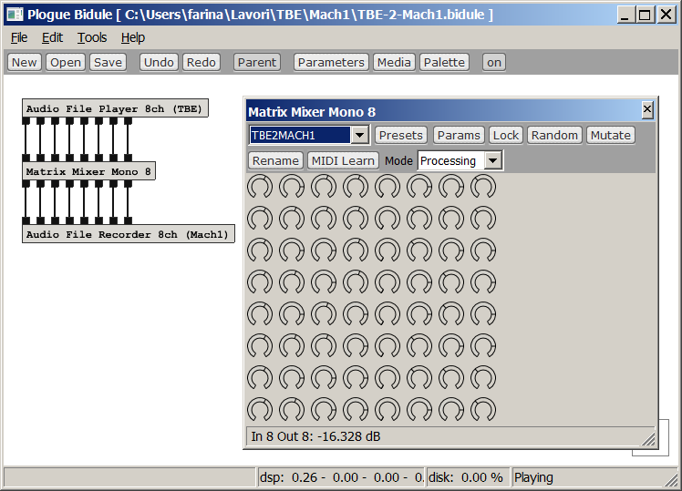
The problem is to setup this module with all the gains contained in the 8x8 matrix shown above.
The user interface allows for entering the gains in dB. And in dB there are no negative-polarity gains...
So this is not the correct way; for entering the proper gains inside the Matrix Mixer 8 module, it was necessary to save a preset and to edit it manually, as shown here:
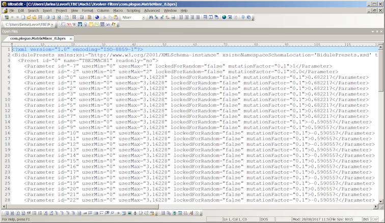
The preset was saved in a file named com.plogue.MatrixMixer_8.bprs (it is a Bidule's preset), which in practice is an XML file, which can be opened and edited with a good text editor.
The 64 gain values of the matrix above has been entered as the values of parameters 0 to 63, one column after the other.
After saving the edited preset and loading it inside the Plogue Bidule module Matrix Mixer Mono 8, the module performs the required conversion from TBE to Mach1 with minimal CPU load (it is just a matrix of gains).
Of course, doing the same in different DAWs can be almost impossible, as only Plogue Bidule comes with this handy matrixing module. Hence, for users of DAWs such as Reaper, the preferred way to operate the conversion from TBE to Mach1 is using the X-volver VST plugin, as explained later, and using the proper FIR filter matrix, named TBE-to-MACH1.wav, which is shown here:
Of course also the inverse transformation is possible.
The conversion had been trivial if the "Spatialiser" plugin included in the Facebook's Spatial Workstation had 8 discrete inputs. Instead, for unknown resons, it was equipped with just 7 inputs, so a single instance of the plugin cannot be used for performing the Mach1 => TBE conversion. Currently one has to use TWO instances of the Spatialer plugin, each dealing with 4 channels, as shown here:
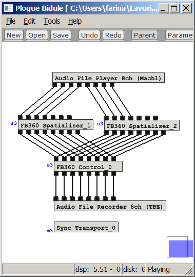
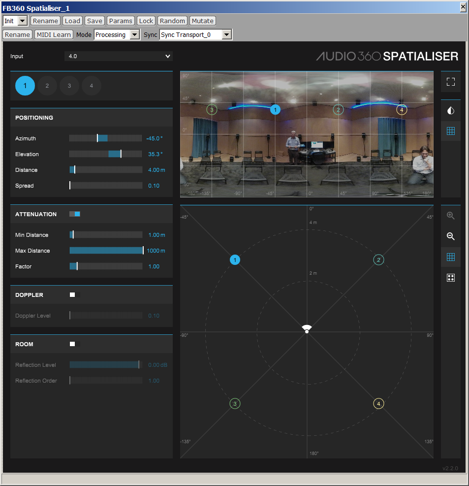
Of course in Spatailser_2 (not shown here) the elevation will be set to -35.3 for all the 4 inputs, the azimuth is the same as in Spatialser_1.
It must also be noted that in Spatialser the azimuth angle has reversed polarity, as the Facebook Spatial Workstation does not comply with ISO standards, hence uses a "wrong" azimuth polarity (positive towards right, whilst the ISO standard is that azimuth is positive towards left).
Finally, it must be noted that the "spread" slider has been set to minimum, for ensuring maximum channel separation, and the distance has been set to 4m.
An alternative way to transform SPS (Mach1) to TBE is to first convert Mach1 to Third Order Amsbionics, as shown in previous chapter, and the convert from Ambisonics to TBE using the guide provided here. However, usually a direct conversion is better than two subsequent ones, even if purely linear as in this case.
All the transcodifications presented here are purely linear operations, so one could think that they are lossless also from a spatial point of view.
Unfortuntaley, this is not true. If we start with an SPS signal, this has the theoretical possibility of infinite channel separation. Which means that we could create a sound field where the sound comes just from one of the SPS directions, and there is no sound coming from elsewhere.
In Ambisonics this is not possible, the sound distribution
is always a continuous balloon. This ballon can be stretched significantly
towards one direction only by using High Order Ambisonics (order 5 or more). But
in practice we are limited to the usage of Ambisonics order 2 or 3, maximum.
This inherently spread the sound all around, reducing spatial "sharpness" in
comparison with the SPS format.
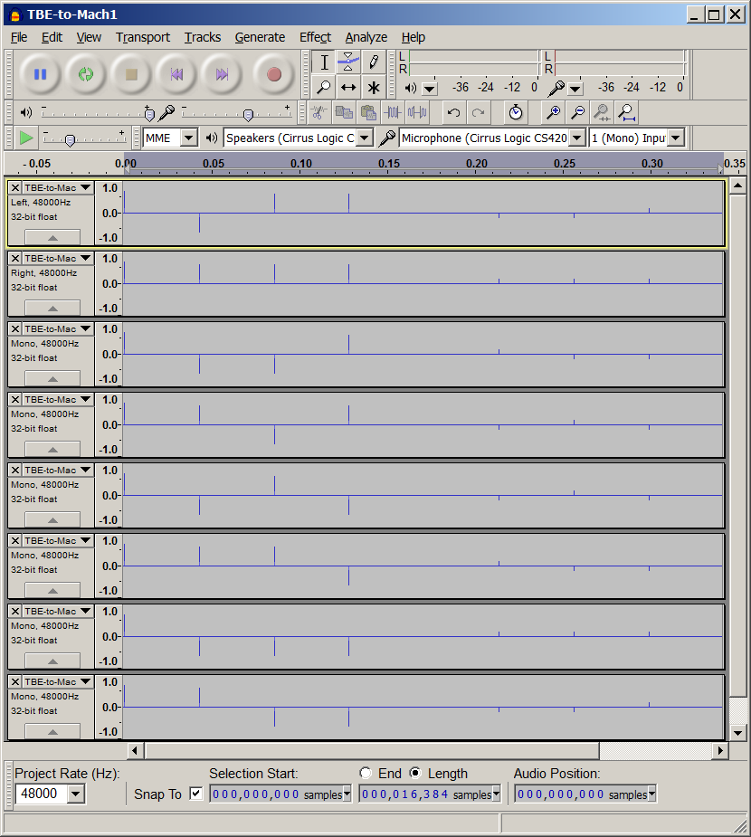
Here we present an example of an SPS-8 (Mach1) signal containing white noise being hardpanned in just one of the 8 channels, namely on channel 2 (Front-Right-Up).
This signal is first converted to TBE, and then converted
back to Mach1, using the conversion methods described in the previous two
chapters.
the following figure shows the Plogue Bidule setup and the VU meters showing the
input and output Mach1 signals:
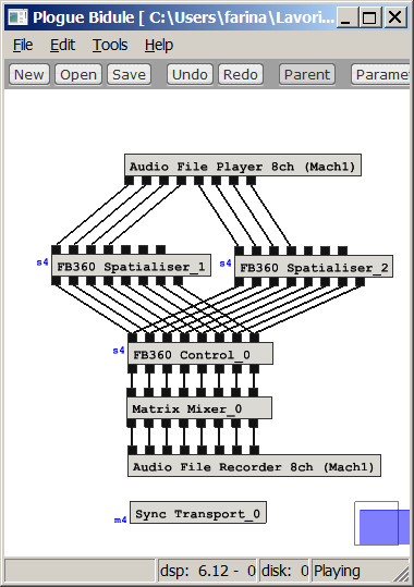
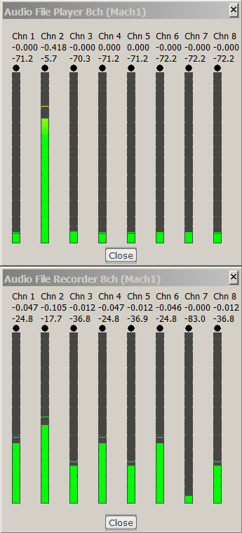
It can be seen that originally there was signal just on
Mach1 channel #2, and after going to TBE format and coming back, now there is
also some signal in adjacent Mach1 channels, and only the channel 7
(Back-Left-Down), being exactly opposite to the channel which was initally
carrying signal, has remained silent.
In practice here you see the gains of second order virtual microphone cardioids,
which are not able anymore to separate perfectly the 8 spatial components of the
original SPS signal.
The lesson here is simple: if you want maximum spatial resolution, you should generate your signals natively in the SPS format, and do all your processing with P-format signals. If, for any reason, you need to switch to Ambisonics and then come back to SPS, you should use very high order Ambisonics (7th order, possible with Ambix plugins) for preserving as much as possible the spatial sharpness of the SPS signal.
If instead you start with low-order Ambisonics signals, for example with the very handy and free Facebook Spatial Workstation, do not think that converting to Mach1 (SPS-8) at the end of your work will increase the spatial resolution: it will remain exactly the same that was available with the TBE format. The only way of improving the spatial resolution is employing not-linear (parametric) processing, such as using Harpex.
If you do not want to deal with the pieces of software
shown above, and you want to use an unique plugin capable of any kind of
transcoding, then
X-volver is for you.
You just need to employ the proper matrix of FIR filters for operating the
transcodification between one format and the other. For example it is shown here
how to use X-volver for converting a 16-channels TOA signal into an 8-channels
Mach1 signal:
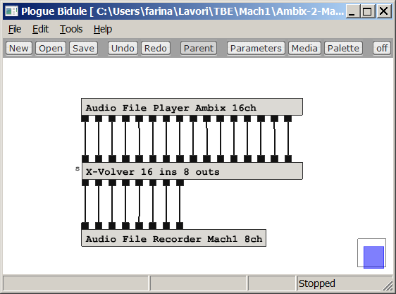
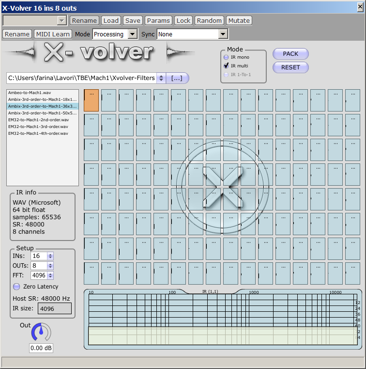
The same approach can be employed also for converting from 1st order Ambisonics, from TBE or from raw 32-channels Eigenmike recordings, or for coming bach from Mach1 to other formats.
The FIR filter matrices for all these possible conversions can be downloaded here:
http://www.angelofarina.it/Public/Xvolver/Filter-Matrices/Mach1-Encoder/
Although currently no native Mach1 microphone is available
on the market yet, some companies such as Brahma and Core Sound are developing
prototypes of these new 8-capsules microphone arrays, as shown here:
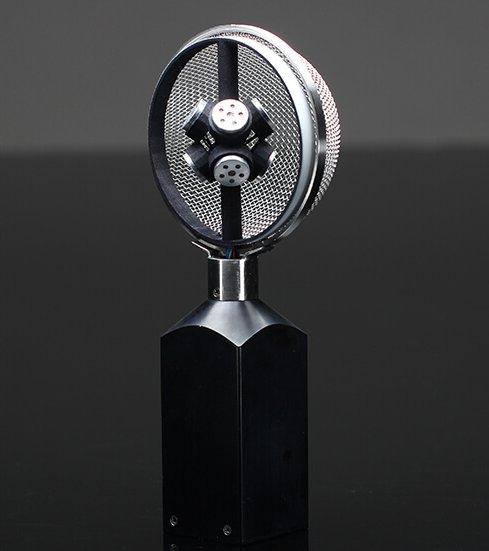
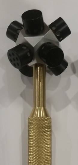
It must be clarified that the raw signals coming out of these 8 capsules are not the Mach1 signals! Please note that:
SPS signals are COINCIDENT, exactly as Ambisonics signals. The 8 capsules of these new microphone array are SPACED by a little amount from the acoustic center of the microphone array, hence if their signals are used as SPS signals, a number of artifacts will occur due to the small delays, such as comb filtering, chorus effect, etc.
Hence for recording a Mach1 stream the 8 capsule signals (A-format) must be converted to SPS (P-format) by means of a proper 8x8 filter matrix, or by means of a dedicated A2P plugin which will be supplied together with the microphone. This also means that, if you are not able to create such an A2P filter matrix, you are discouraged to build yourself an 8-capsule microphone array for performing native Mach1 recordings.
As of today, it is possible to record native Mach1 signals employing existing high order microphone arrays, such as the Eigenmike or our own AIDA-RAI cylindrical microphone array:
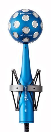
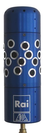
Eigenmike (Left) and RAI-AIDA Cylindrical Microphone Array (Right)
From a 32-channels raw recording (A-format) coming form one of these high-end microphone arrays it is quite easy to derive directly a set of directive virtual microphones with proper directivity and aiming (P-format), employing the software tools provided with them (Eigenstudio and 3DVMS respectively). For example, here it is shown how to create the 8 Mach1 signals from an Eigenmike recording:
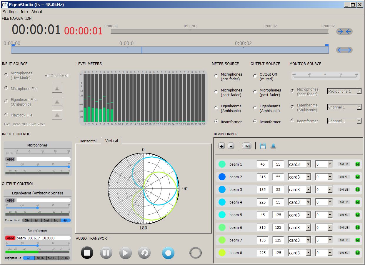
In this case it is possible to adjust the beamwidth
of the virtual microphones, choosing among cardioids of order 2, 3 and 4.
The results are significantly better than first creating TOA signals (B-format) and then
transcoding them as shown in previous chapter, as a single filtering stage going
directly from A-format to P-format is
always better than two, and making a direct beamforming of the capsule signals
avoids some of the known problems of High Order Ambisonics occurring at very low
and very high frequencies.
So currenty using an Eigenmike with direct beamforming of the 8 signals is the
preferred method for obtaining high quality spatial audio recordings in Mach1
format. This can also be operated in realtime, with reasonably small latency, so
the Mach1 signals can be used even for live streaming.
Here it is shown instead how to use the 3DVMS software developed for the RAI-AIDA Cylindrical array (this software, indeed, can be used also for other microphone arrays, such as the Eigenmike, planar and dome arrays with various number of capsules):
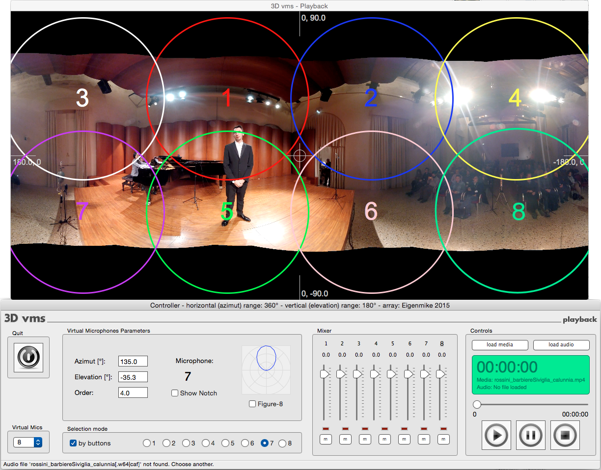
In this case the directivity pattern of the virtual microphones can be changed smoothly from order 0.0 (omni) up to order 8.0, but of course for generating an SPS-8 (Mach1) stream the 8 virtual microphones should be chosen in the range of orders 2.0 to 4.0.
1. Sideloading
Here we provide instructions and examples for creating 360 videos including a Mach1 8-channels soundtrack, which can be side-loaded on a Samsung Gear VR device, for being viewed with the Samsung VR app.
The container must be a MP4 file, and the video must be an equirectangular panoramic video, either monoscopic (2:1 format) or sterescopic top-bottom (1:1 format).
Recommended resolutions are 3840x1920 or better for monoscopic, 3840x3840 for stereoscopic.
The Samsung VR app can decode smoothly both H264 and H265 videos. Of course the latter is recommended, providing faster downloads and better quality.
Indeed, the equirectangular 4k H264 video coming from a Samsung Gear 360 camera is just perfect, as it could be expected.
Coming to the soundtrack, Samsung VR supports natively the Mach1 8-channels spatial audio format. But the soundtrack cannot be stored as a single stream containing the 8 channels, as the Samsung VR app cannot understand this format. It is necessary to split the 8 channels in 4 stereo soundtracks (2 channels each), and pack these 4 streams together with the video stream inside the MP4 container as 4 separate AAC streams.
This can be done with the command line tool called FFMPEG. Suppose that we have an H264 video file called test.mp4 and an 8-ch WAV file (48 kHz, 16 bits) called test.wav. The following commands first split the 8-channels WAV file in 4 stereo WAV files (1.wav, 2.wav, 3.wav, 4.wav), and then create a new MP4 file with the proper contents (and proper file name) for being side-loaded onto a Gear VR device running the Samsung VR app:
|
ffmpeg -i test.wav -map_channel 0.0.0 -map_channel 0.0.1 1.wav -map_channel 0.0.2 -map_channel 0.0.3 2.wav -map_channel 0.0.4 -map_channel 0.0.5 3.wav -map_channel 0.0.6 -map_channel 0.0.7 4.wav ffmpeg -i test.mp4 -i 1.wav -i 2.wav -i 3.wav -i 4.wav -map 0:v -map 1:a -map 2:a -map 3:a -map 4:a -c:v copy -c:a aac -shortest test_m1spatial.mp4 |
Please note that the filename of the resulting file, to be side-loaded in the Gear VR device, ends with _m1spatial : this is required for the Samsung VR player app for Gear VR to understand that this is a file containing a Mach1 spatial audio soundtrack.
At this point you connect your Samsung S6/S7/S8/Note8 smartphone (or your Oculus Go) to your computer with an USB cable and copy the processed file into the /MilkVR folder, which is where the Samsung VR app for Gear VR expects to find them. Doing so, the sideloaded videos will appear in Samsung VR under the "Sideloaded" tab.
2. Uploading to the Samsung VR portal
![]() Attention:
Samsung VR finally fixed (un July 2018) the issues on their web portal, so no dirty tricks are required anymore
Attention:
Samsung VR finally fixed (un July 2018) the issues on their web portal, so no dirty tricks are required anymore
After testing your video file by sideloading it on your Gear VR device, you can upload it onto the Samsung VR Portal web site, for making it available to others either in streaming or for downloading.
Be aware that the video to be uploaded is different form the one you tested locally by sideloading, as explained here:
https://samsungvr.com/portal/content/content_specs
On that page it is written what follows:
Mach1 Spatial Audio
All 8 channels are to be placed in a single audio track. The audio track will be transcoded to 4 audio tracks with 2 channels each to support the Android platform. |
|
ffmpeg -i test.mp4 -i test.wav -map 0:v -map 1:a -c:v copy -c:a copy -shortest test_m1spatial.mov |
On this page you specify title and informations on your video, and you must also set some parameters, in particular the format for the video file (Stereoscopic Type equal to "none", as it is monoscopic) and for Audio Type:
ATTENTION !!! Here is the trick! You must leave it to "autodetect"!
You can also add tags. The upload is usually quite fast, but after it, you have to wait for a much longer time, during which the uploaded contents are reformatted with different codecs, suitable for the different platforms which can access the Samsung VR contents.
When finally the processing is finished, you can search for your video online, using the search button while wearing your Samsung Gear VR or Oculus Go HMD....
3. Sample files
The sample audio and video files (test.wav, test.mp4) employed for the FFMPEG commands in the two previous subchapters can be found here:
http://www.angelofarina.it/Public/Xvolver/Filter-Matrices/Mach1-Encoder/Samples/
All the contents are Copyright by Angelo Farina, 2017-2018