|
1
|
- Angelo Farina and Lamberto Tronchin
|
|
2
|
|
|
3
|
|
|
4
|
|
|
5
|
|
|
6
|
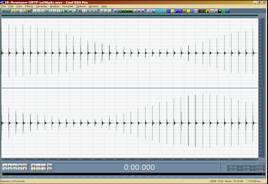
|
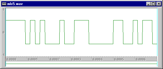
|
7
|
|
|
8
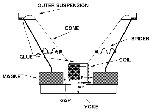
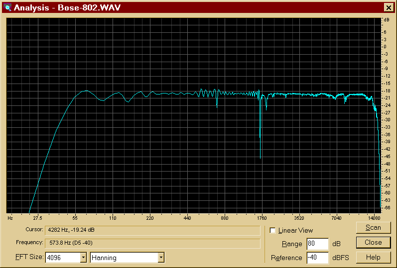
|
|
|
9
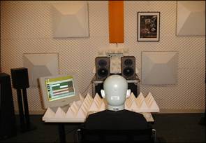
|
|
|
10
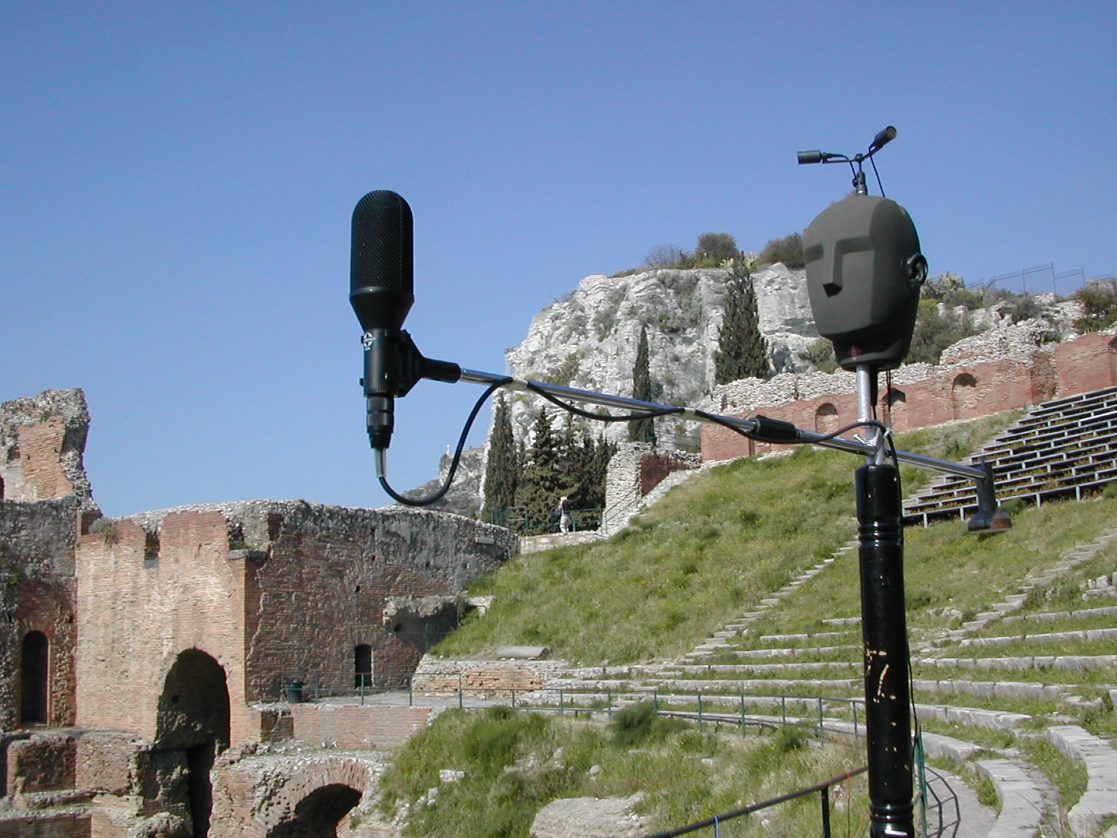
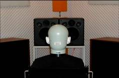
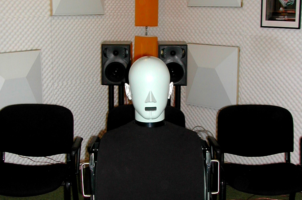
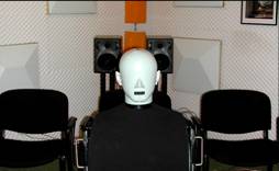
|
|
|
11
|
|
|
12
|
|
|
13
|
|
|
14
|
|
|
15
|
|
|
16
|
|
|
17
|
|
|
18
|
|
|
19
|
|
|
20
|
|
|
21
|
|
|
22
|
|
|
23
|
|
|
24
|
- We are interested in the linear impulse response h(t). This can be
estimated by the knowledge of the input signal x(t) and of the output
signal y(t).
- The influence of the not-linear part K and of the noise n(t) has to be
minimized.
|
|
25
|
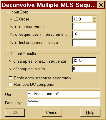
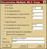
- X(t) is a periodic binary signal obtained with a suitable
shift-register, configured for maximum lenght of the period.
|
|
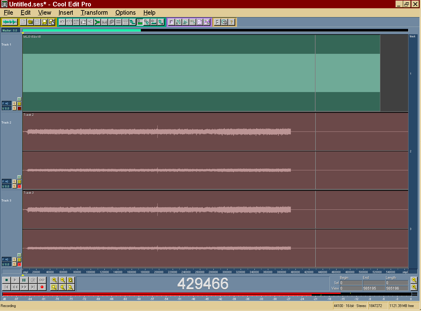
26
|
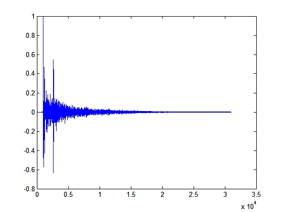
- The re-recorded signal y(i) is cross-correlated with the excitation
signal thanks to a fast Hadamard transform. The result is the required
impulse response h(i), if the system was linear and time-invariant
|
|
27
|
|
|
28
|
|
|
29
|
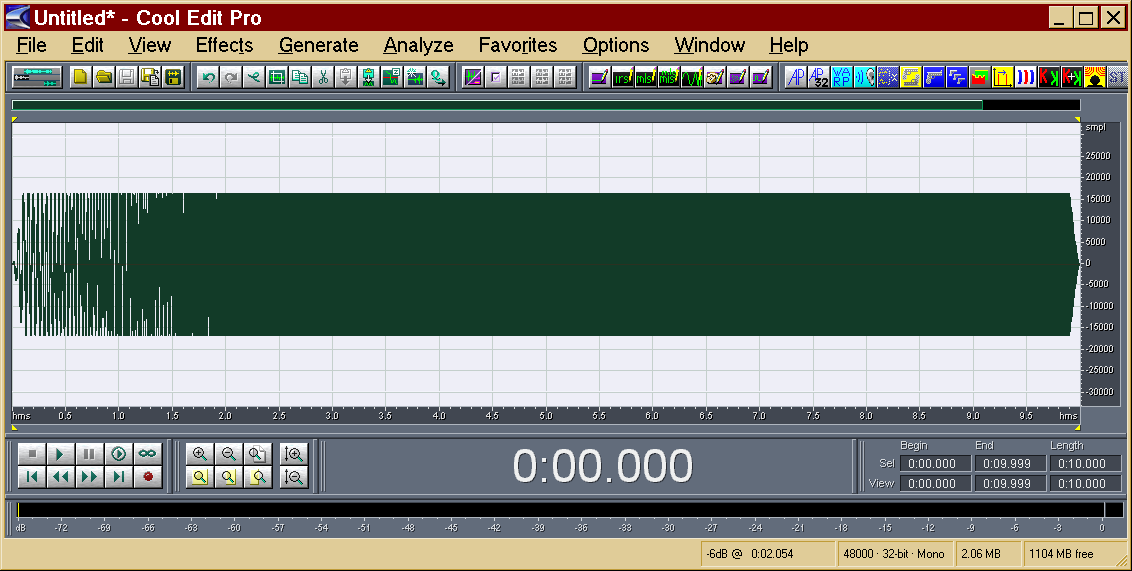
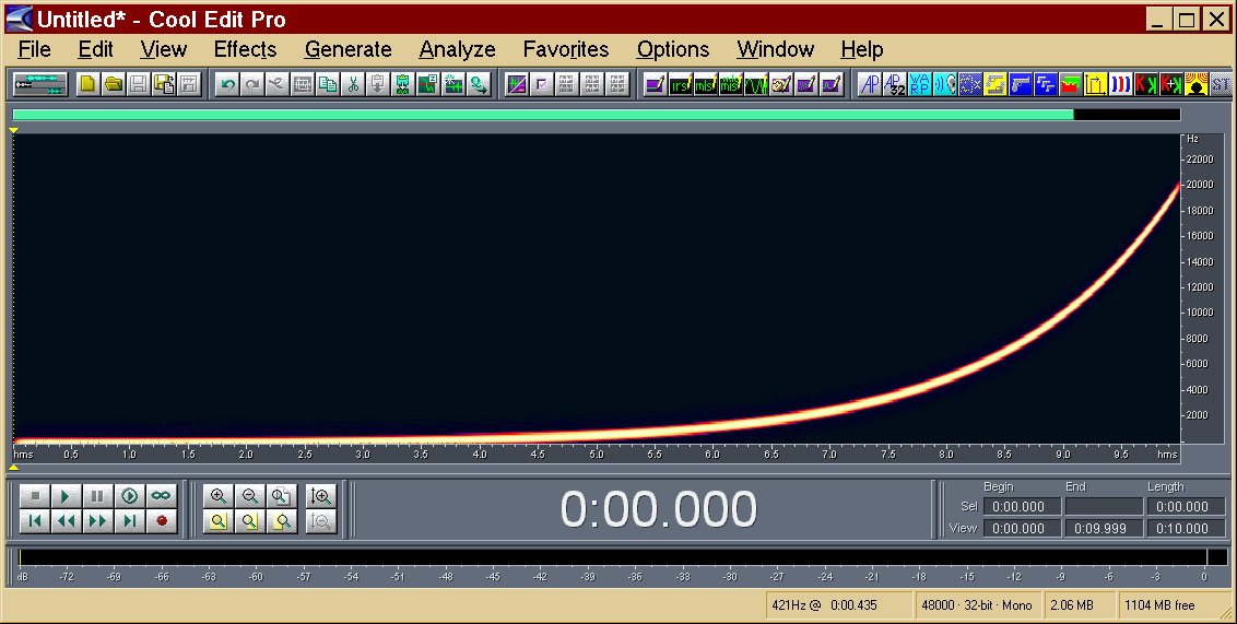
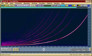
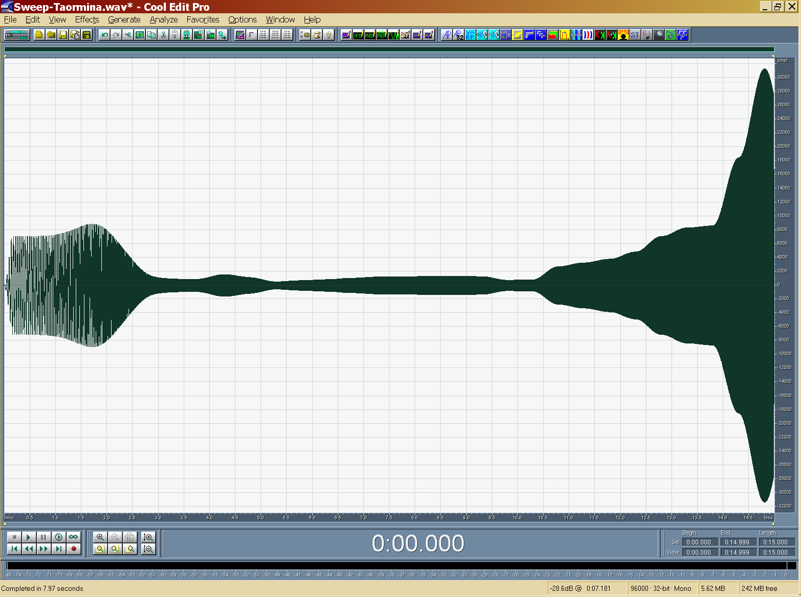
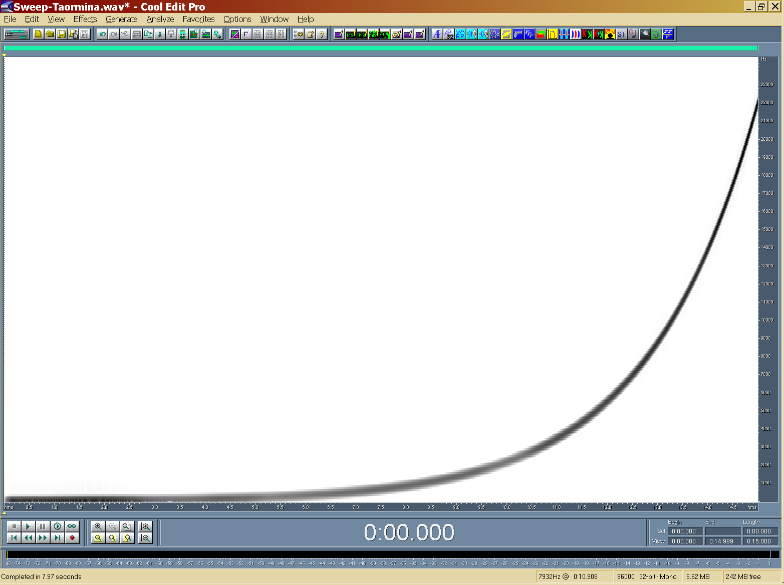
- x(t) is a sine signal, which frequency is varied exponentially with
time, starting at f1 and ending at f2.
|
|
30
|
|
|
31
|
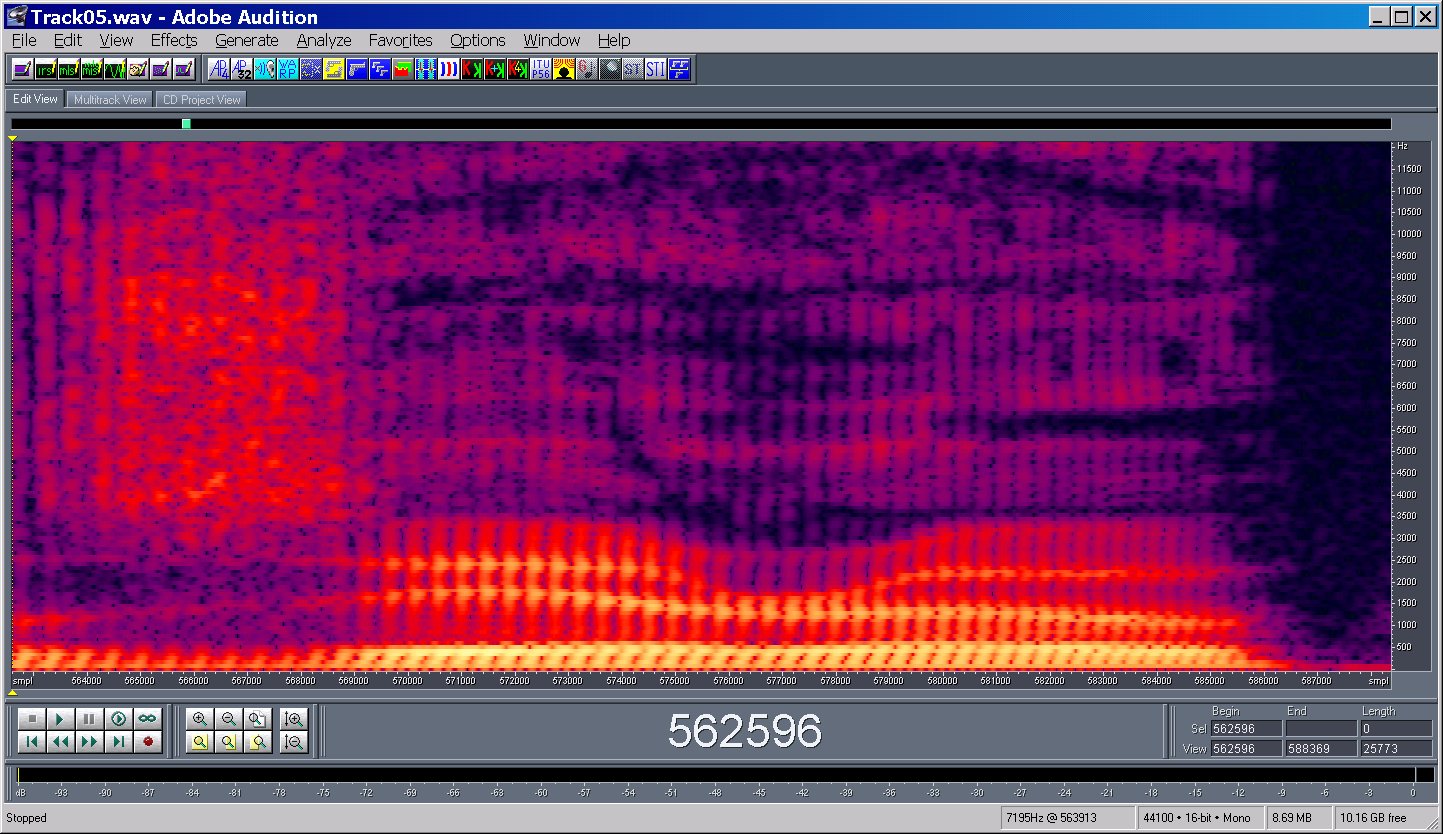
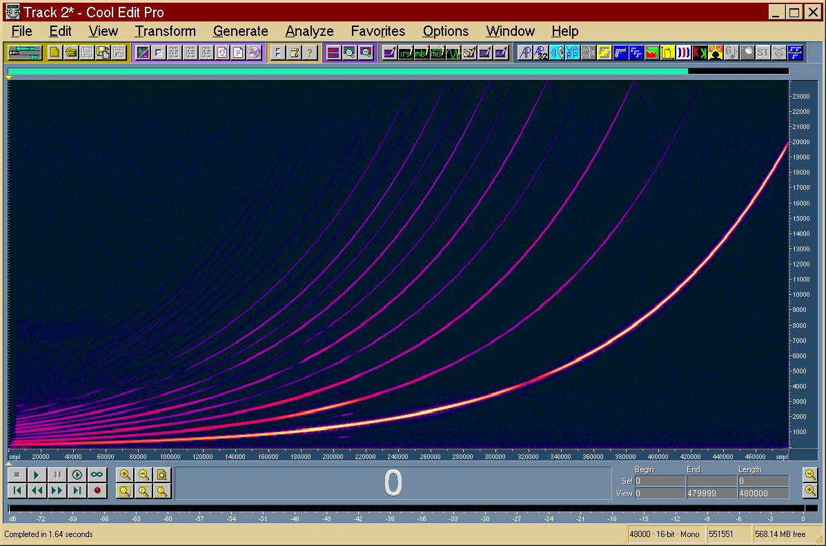
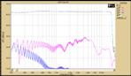
- The not-linear behaviour of the loudspeaker causes many harmonics to
appear
|
|
32
|
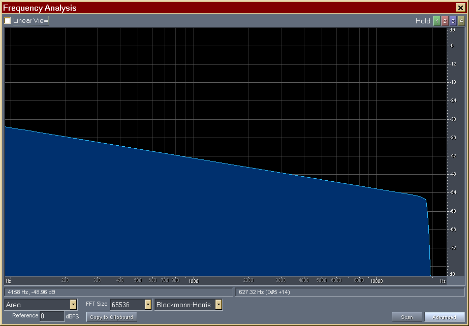
- The “time reversal mirror” technique is employed: the system’s impulse
response is obtained by convolving the measured signal y(t) with the
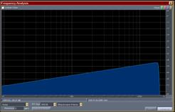
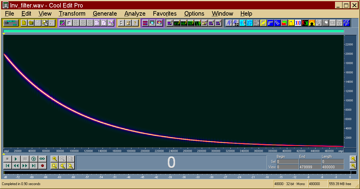
time-reversal of the test signal x(-t). As the log sine sweep does not
have a “white” spectrum, proper equalization is required
|
|
33
|
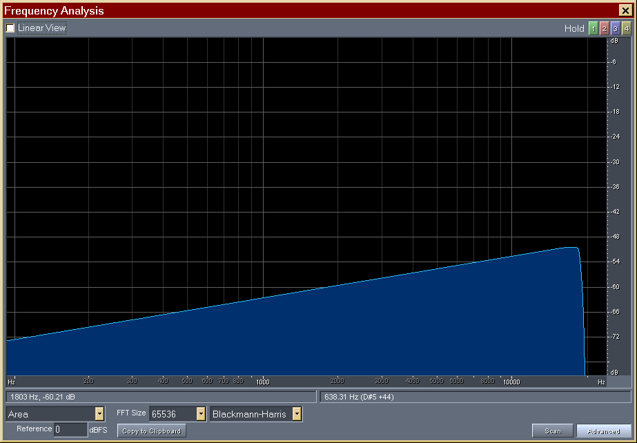
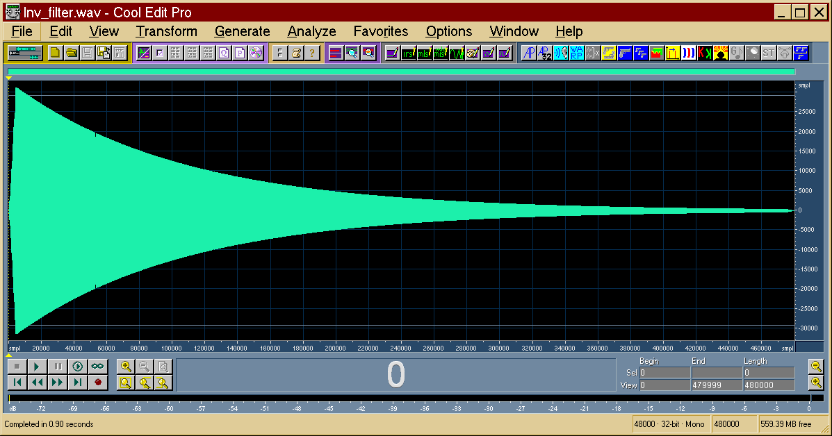
- The deconvolution of the IR is obtained convolving the measured signal
y(t) with the inverse filter z(t) [equalized, time-reversed x(t)]
|
|
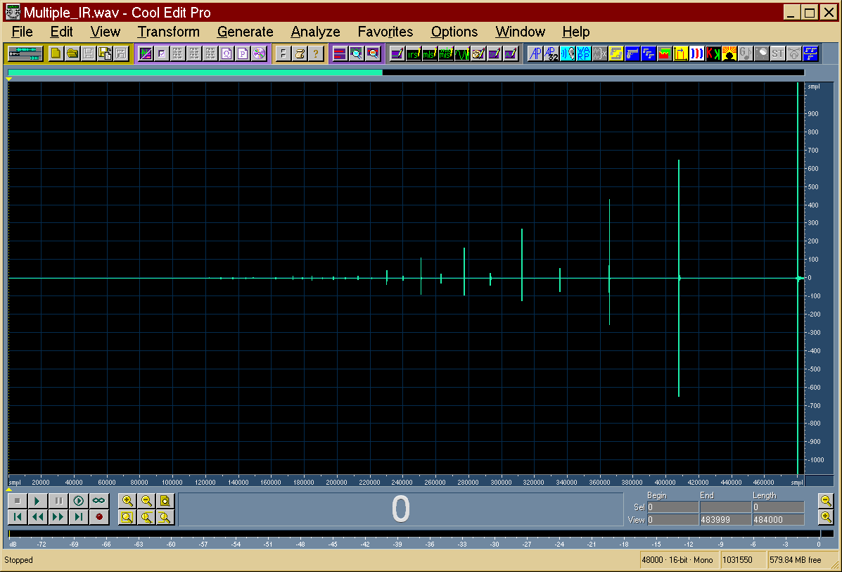
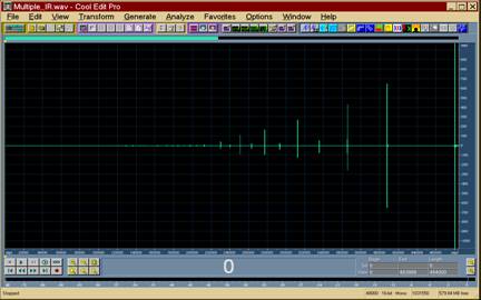
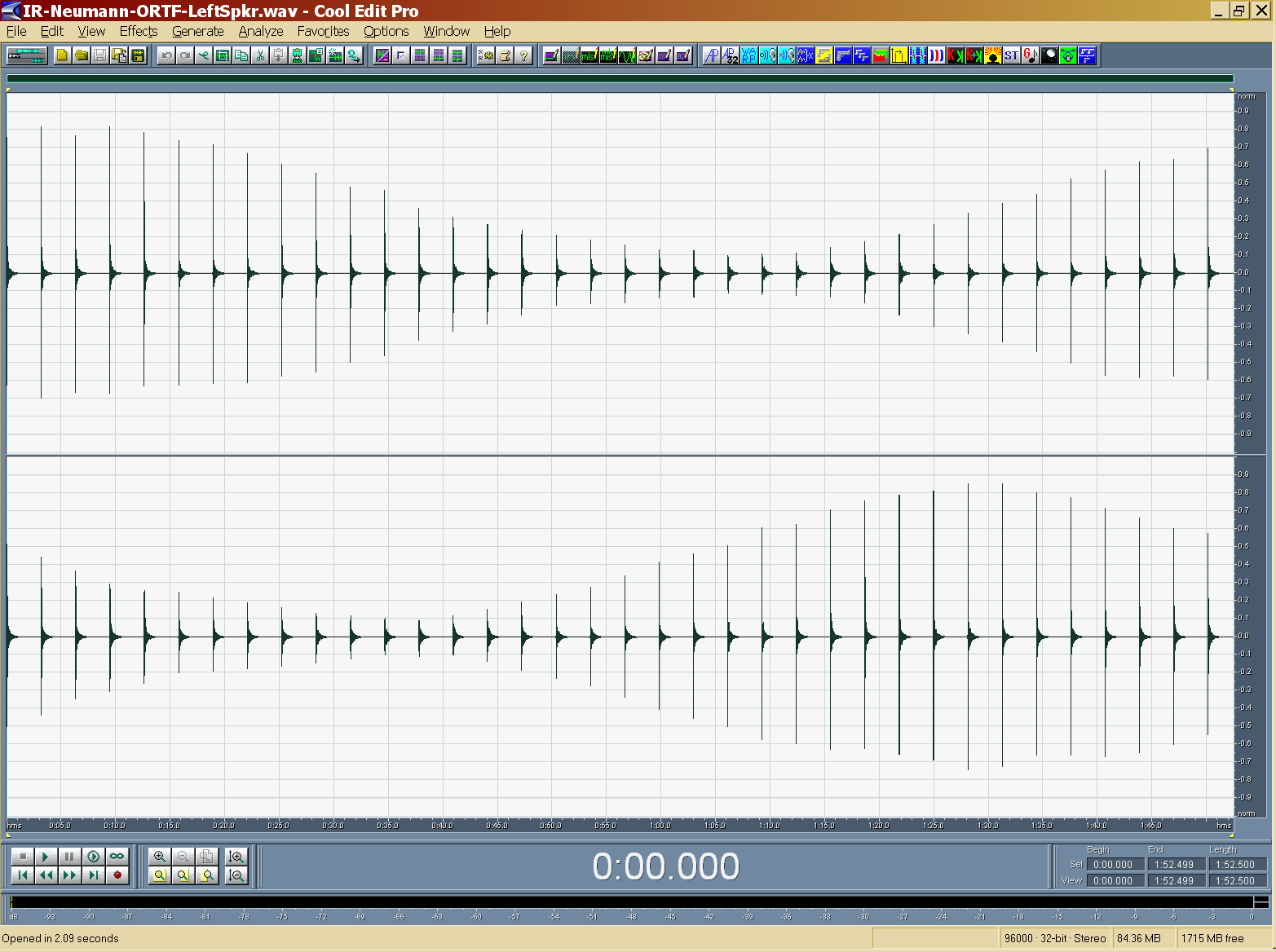
34
|
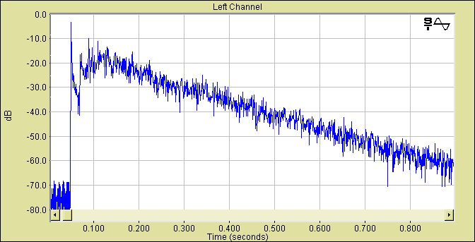
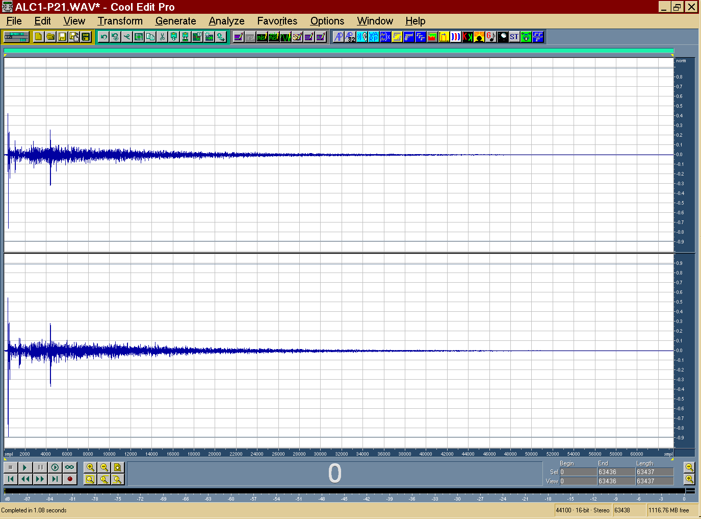
- The last impulse response is the linear one, the preceding are the
harmonics distortion products of various orders
|
|
35
|
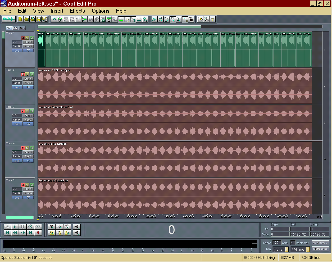
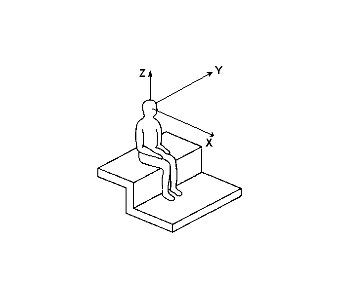
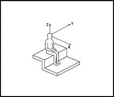
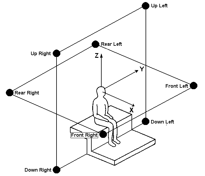
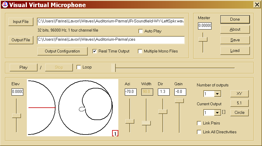
- It is possible to measure impulse responses in various formats:
- Mono (Omnidirectional)
- Stereo (ORTF)
- Binaural (Dummy Head)
- B-format (1st order Ambisonics, Soundfield microphone)
- WFS (Wave Field Synthesis, circular array)
- M. Poletti high-order virtual microphones
- Employing a multichannel sound card, all of these measurements can be
performed simultaneously
|
|
36
|
- Test Signal: pre-equalized sweep
|
|
37
|
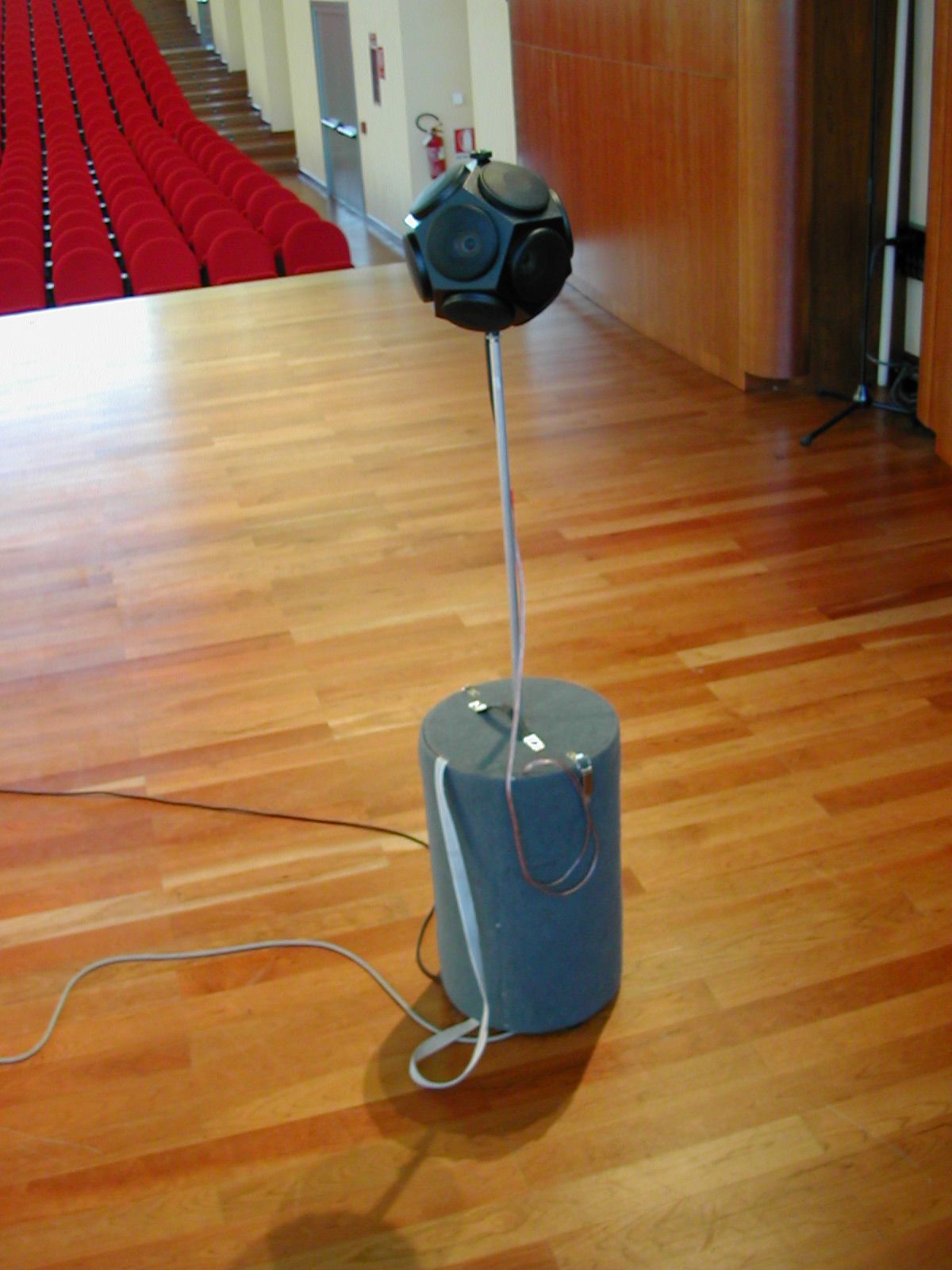
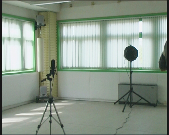
- Equalized, omnidirectional sound source:
- Dodechaedron for mid-high frequencies
- One-way Subwoofer (<120 Hz)
|
|
38
|
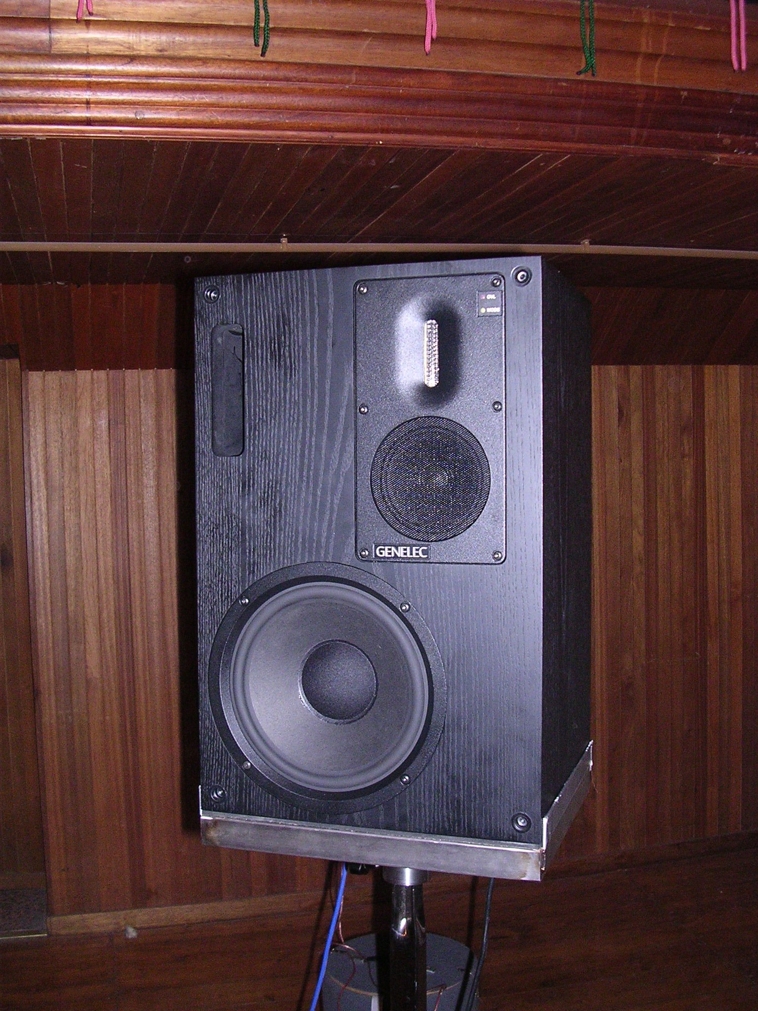
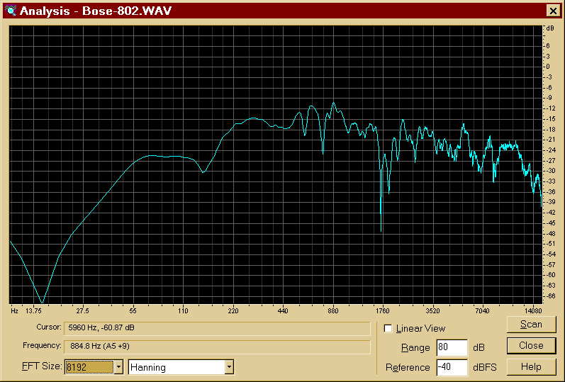
- Genelec S30D reference studio monitor:
- Three-ways, active multi-amped, AES/EBU
- Frequency range 37 Hz – 44 kHz (+/- 3 dB)
|
|
39
|
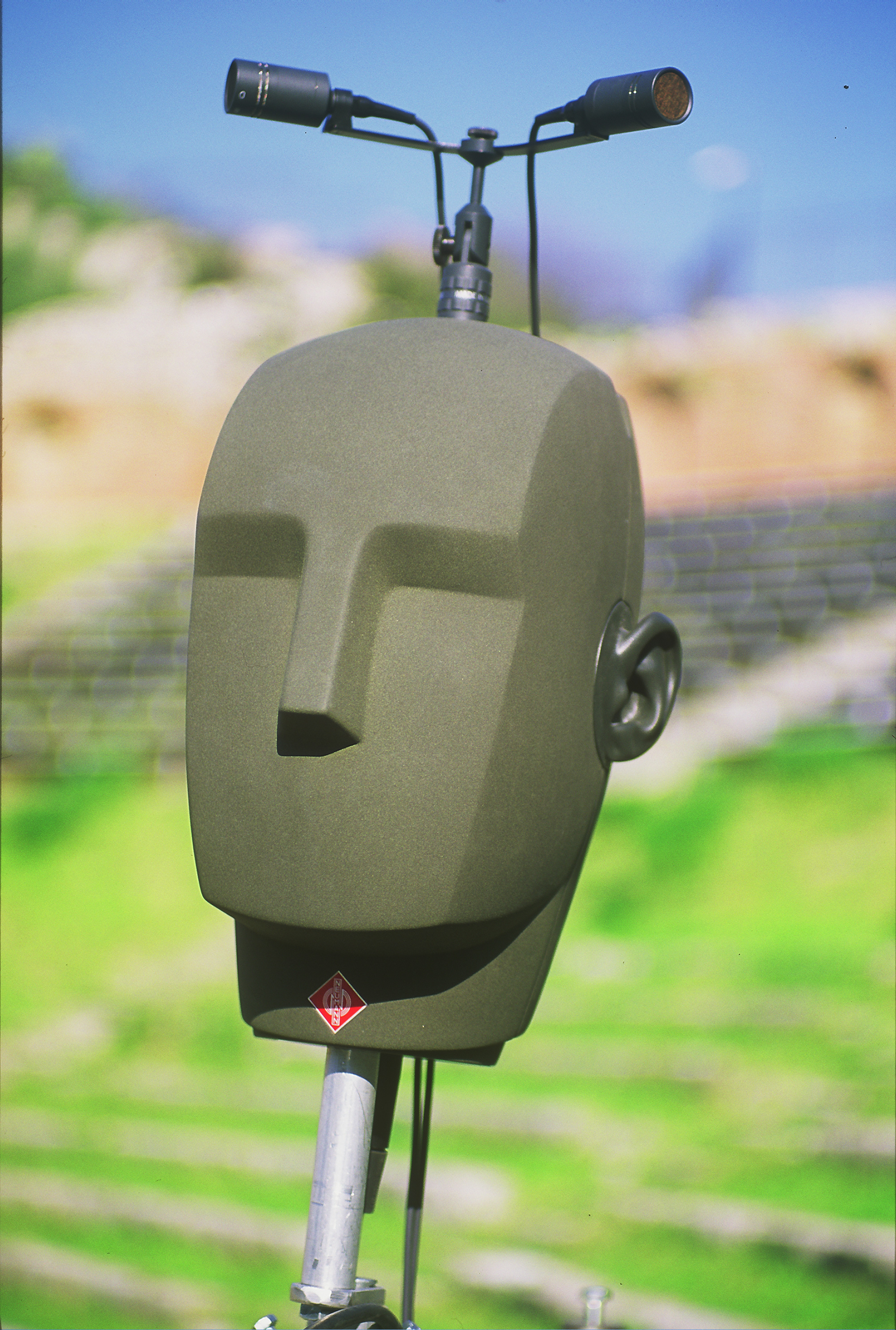
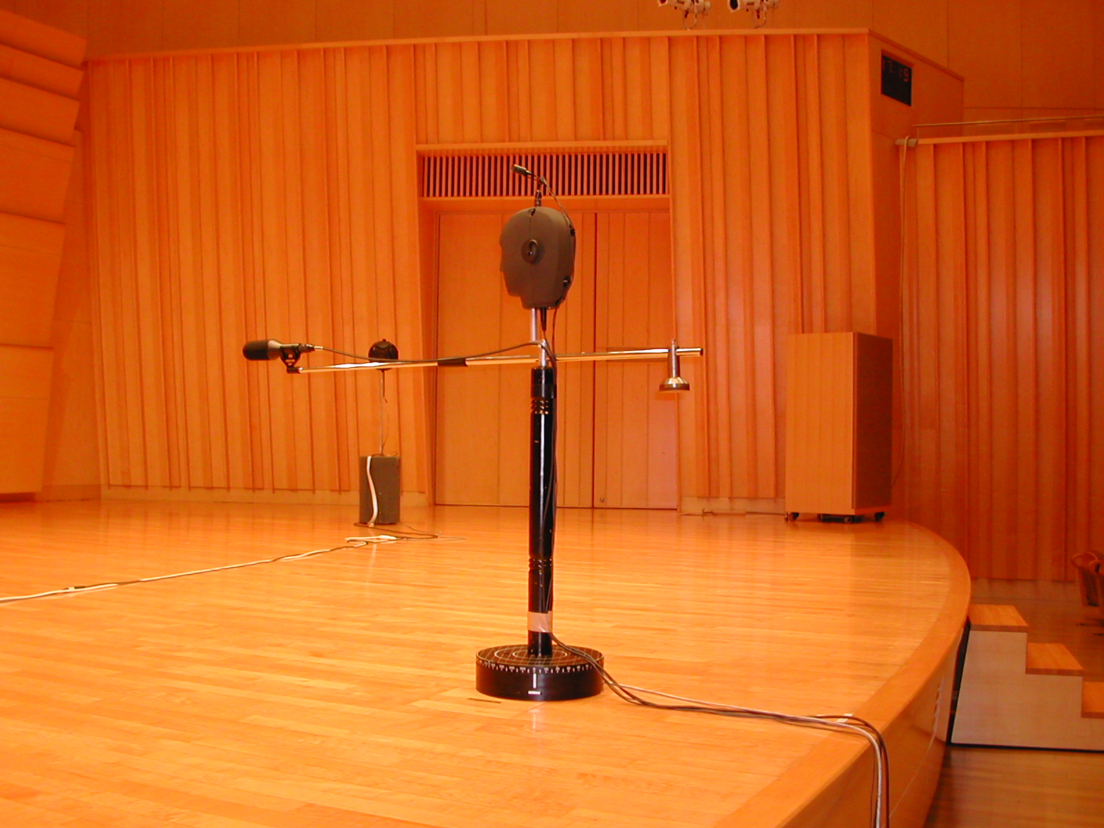
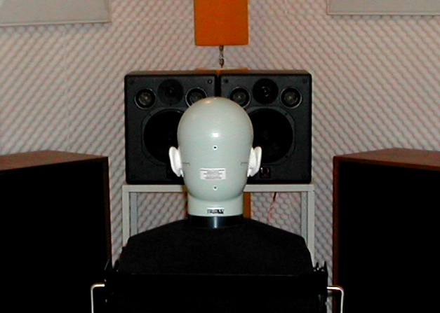
- 3 types of microphones:
- 2 Cardioids in ORTF placement (Neumann K-140)
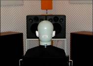
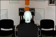
- Binaural dummy head (Neumann KU-100)
- B-Format 4 channels (Soundfield ST-250)
|
|
40
|
|
|
41
|
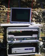
- A single measurement session play backs 36 times the test signal, and
simultaneusly record the 8 microphonic channels
|
|
42
|
|
|
43
|
|
|
44
|
|
|
45
|
|
|
46
|
|
|
47
|
|
|
48
|
|
|
49
|
|
|
50
|
|
|
51
|
|
|
52
|
|
|
53
|
|
|
54
|
|
|
55
|
|
|
56
|
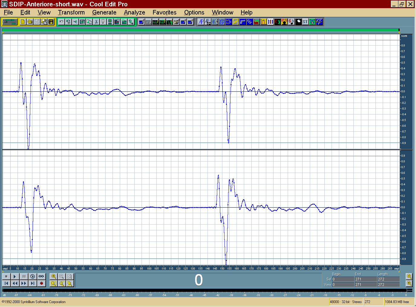
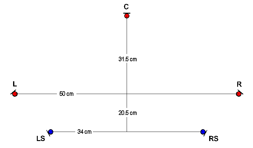
- Stereo (ORTF on 2 standard loudspeakers at +/- 30°)
- Binaural on headphones
- Binaural on loudspeakers (Stereo Dipole)
- Full 3D Ambisonics 1st order (decoding the B-format signal)
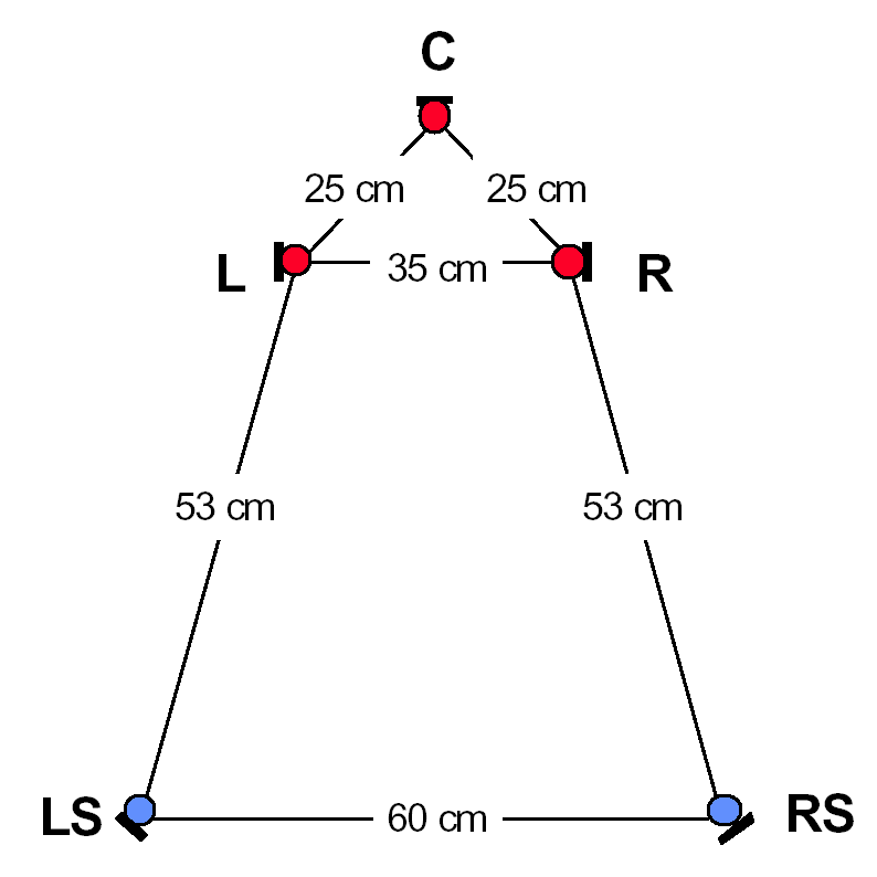
- ITU 5.1 (from different 5-mikes layouts)
- 2D Ambisonics 3rd order (from Mark Poletti’s circular array
microphone)
- Wave Field Synthesis (from the circular array of Soundfield microphones)
- Hybrid methods (Ambiophonics)
|
|
57
|
|
|
58
|
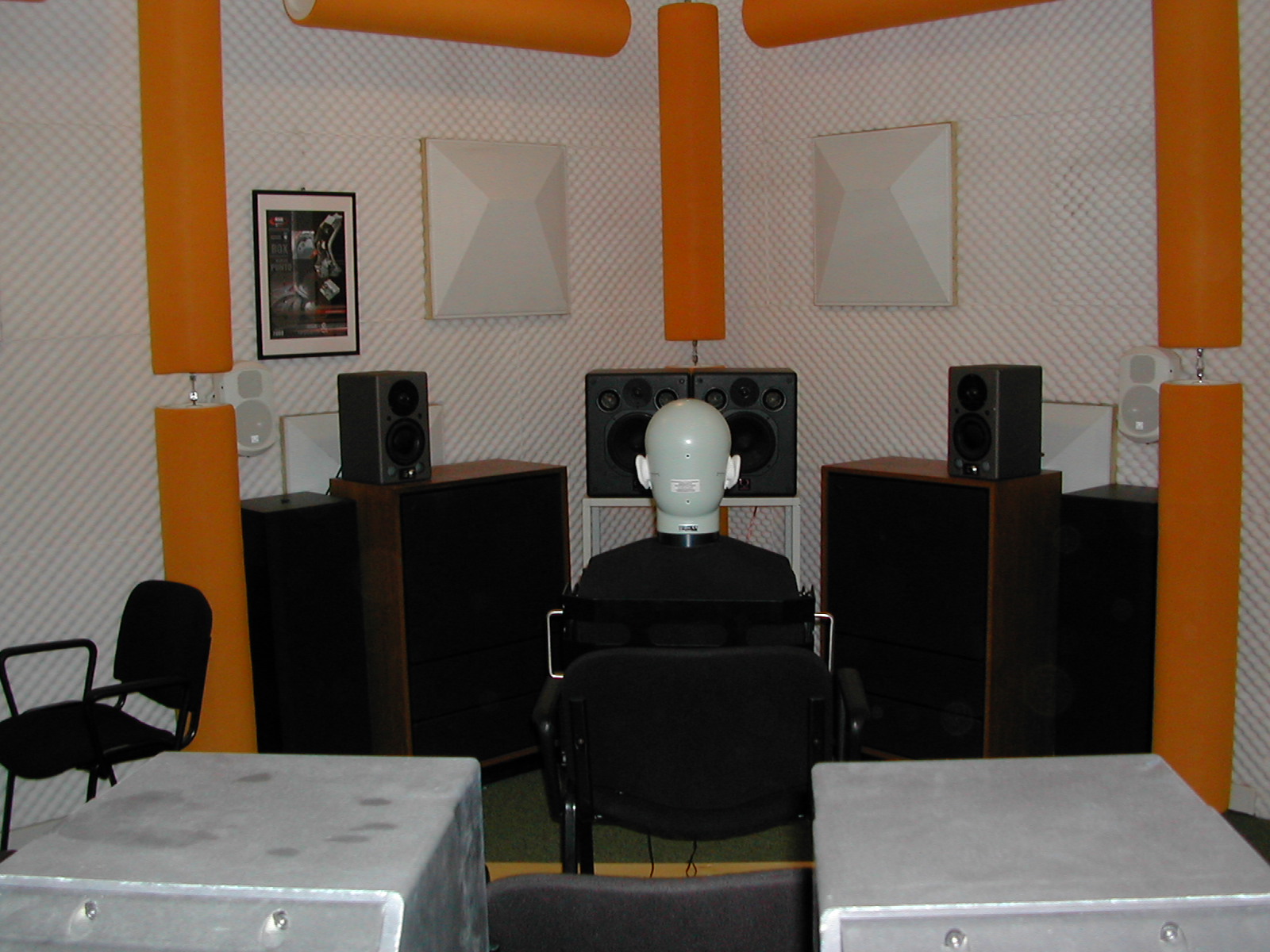
- Playback occurs over a pair of loudspeakers, in the standard
configuration at angles of +/- 30°, each being fed by the signal of the
corresponding microphone
|
|
59
|
|
|
60
|
|
|
61
|
|
|
62
|
- Step 1 – pass to frequency domain through FFT
|
|
63
|
|
|
64
|
- System’s impulse response
|
|
65
|
- Convolution of inverse filter with the system’s impulse response
|
|
66
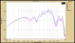
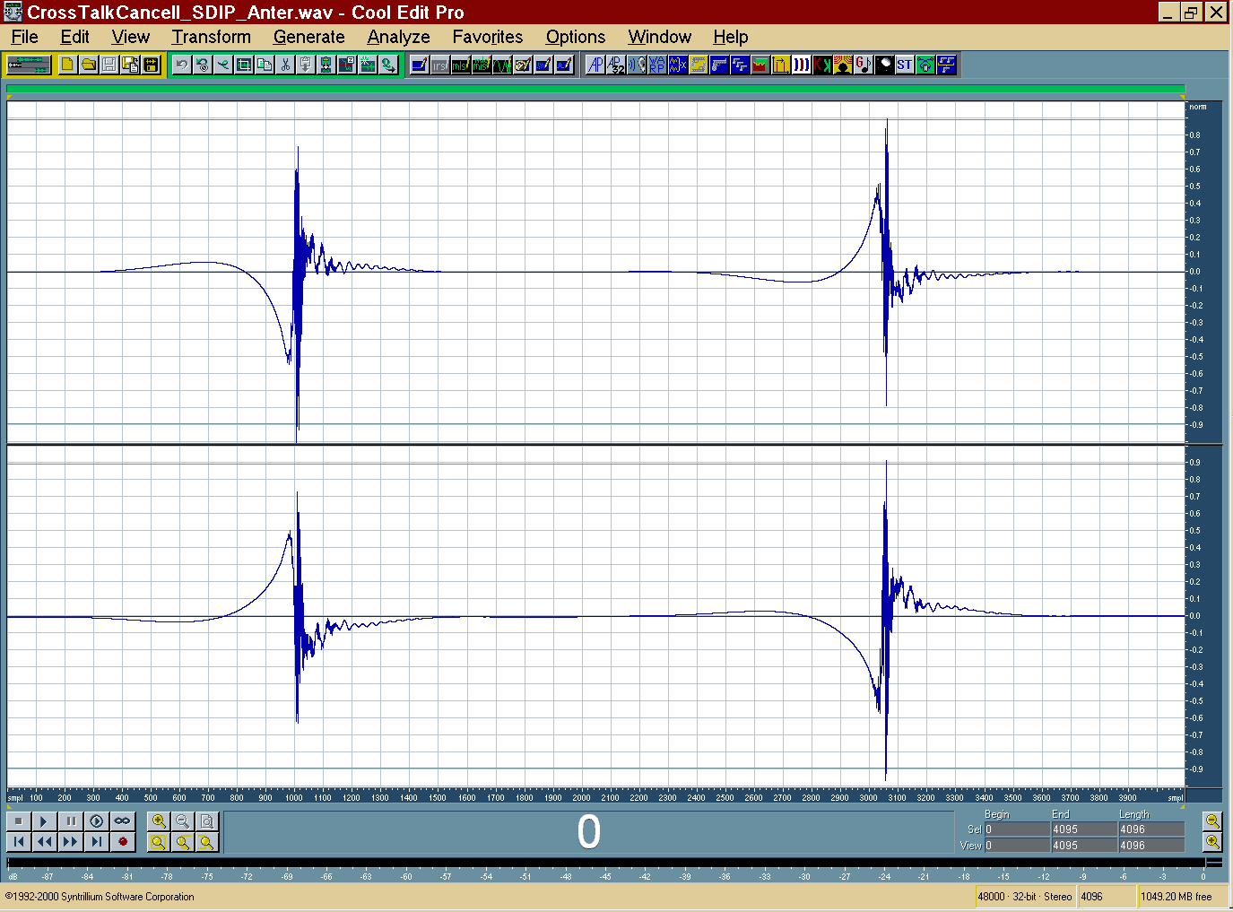
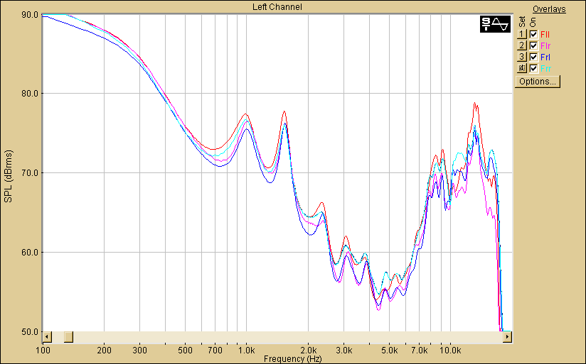
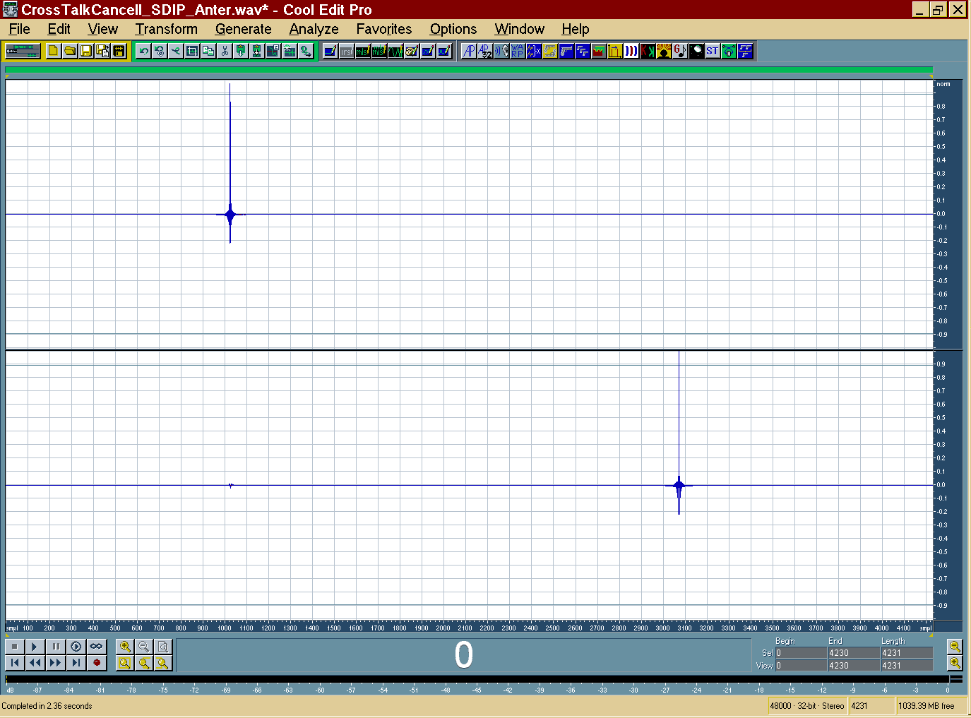
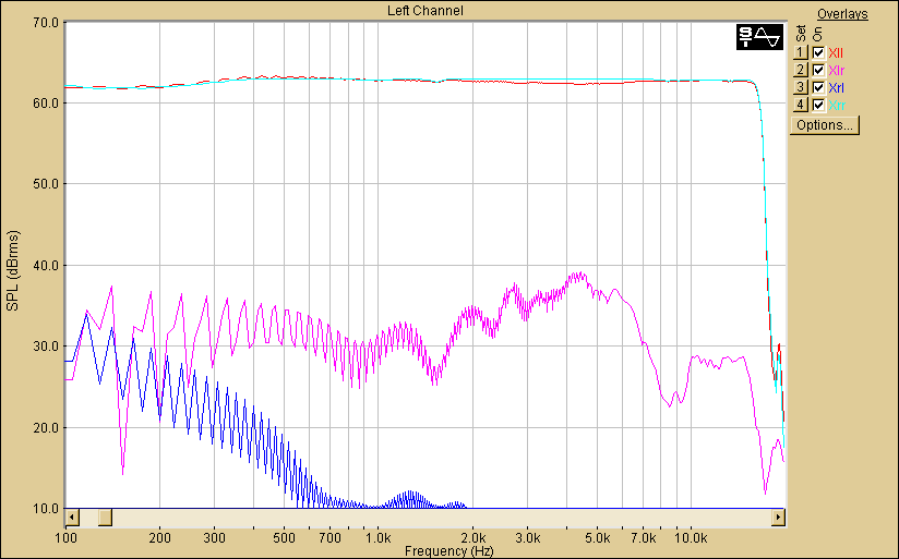
|
- Reproduction occurs over 2 loudspeakers angled at +/- 10°, being fed
through a “cross-talk cancellation” digital filtering system
|
|
67
|
|
|
68
|
|
|
69
|
|
|
70
|
|
|
71
|
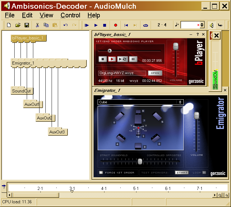
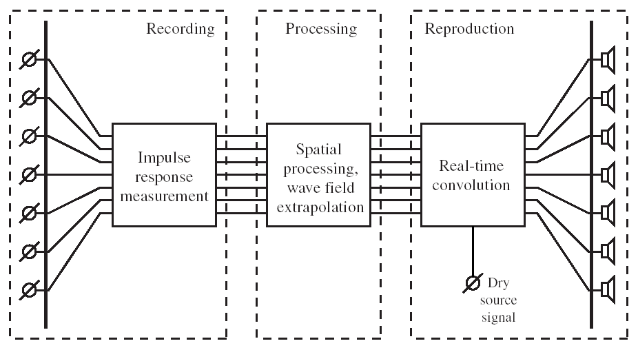
- Reproduction occurs over an array of 8-24 loudspeakers, through an
Ambisonics decoder
|
|
72
|
|
|
73
|
|
|
74
|
|
|
75
|
|
|
76
|
|
|
77
|
|
|
78
|
|
|
79
|
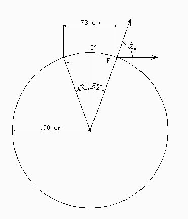
- One of the two ORTF cardioid is employed, which samples 36 positions
along a 110 mm-radius circumference
|
|
80
|
- Flow diagram of the process
|
|
81
|
- Stereo Dipole + Virtual Ambisonics
|
|
82
|
|
|
83
|
|
|
84
|
|
|
85
|
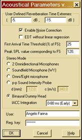
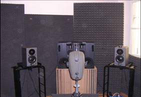
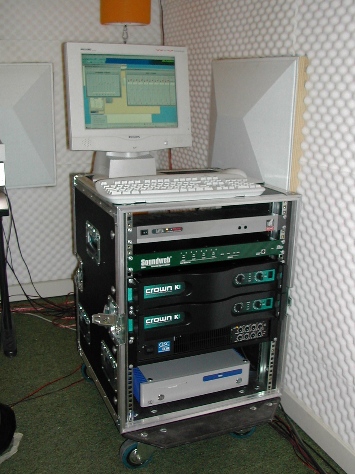
- The experimental setup allows for measurements of high-quality mono,
binaural and B-format IRs
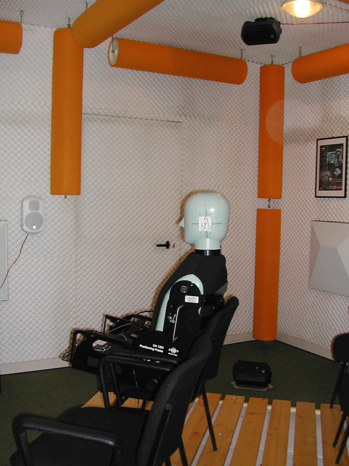
- A proper listening room is required in order to reproduce sound field
with Stereo Dipole and/or Ambisonic methodology
- The sound quality of different theatres can be assessed in real-time in
the listening room
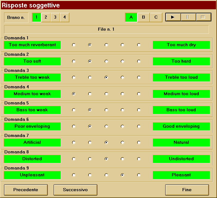
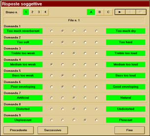
- Questionnaires can be collected through an interactive-driven software
|
|
86
|
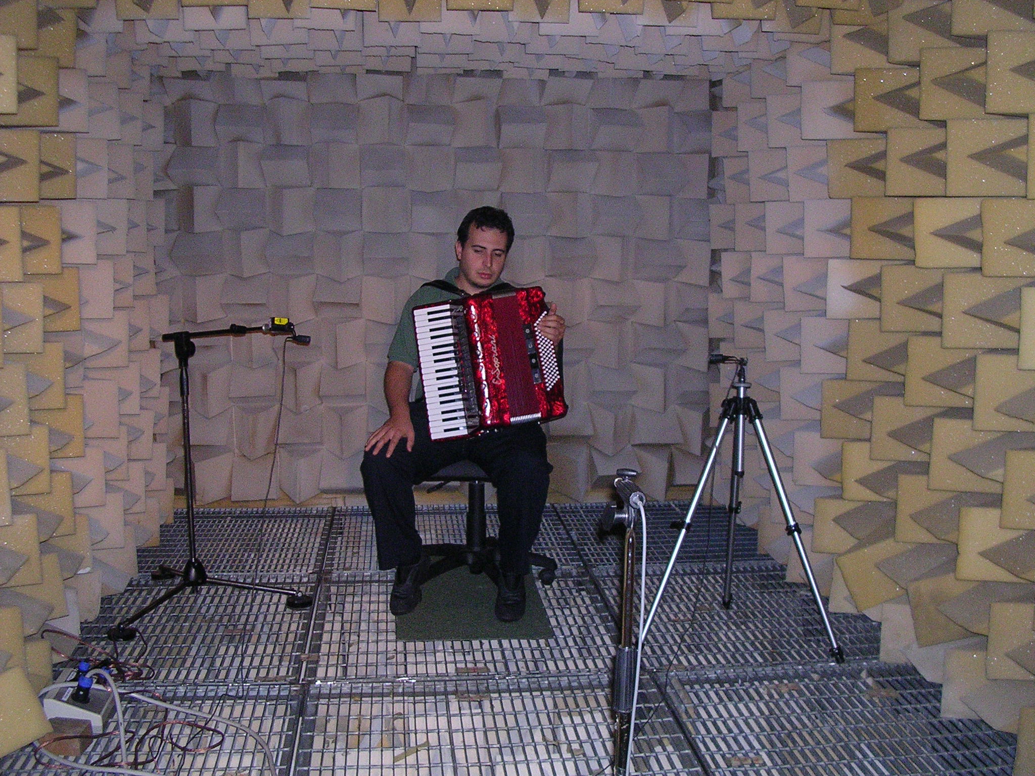
- Thanks to novel zero-latency convolution software, musicians can play a
keyboard and listen to a virtual spatial sound environment in real time.
- Spatial auralisation can be imediately switched or morphed while the
musician plays the keyboard.
- This technology has been made avaliable also for processing music in
recording studios, thanks to plugins developed by Sony, Waves, Voxengo,
Tascam, Altiverb
- The next step will be to port this “sampled reverberation” method also
for live applications
|

 Notes
Notes