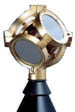
Soundfield ST-250
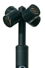
Soundfield STS-200
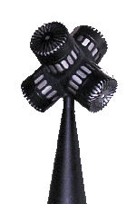
DPA-4
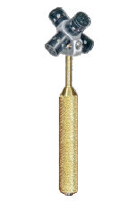
Core Sound TetraMic
(C) by Angelo Farina, University of Parma, Italy
This page deals with the problem of converting the 4 signals coming from the capsules of a Soundfield-like microphone, collectively called A-format, to a standard B-format signal.
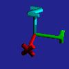
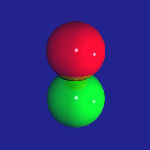
First of all, these Soundfield-like microphones employ 4 cardioid or subcardioid capsules, arranged (more or less) as a tetrahedron, as shown in the following pictures (all mikes seen from "front"):
|
Soundfield ST-250 |
Soundfield STS-200 |
DPA-4 |
Core Sound TetraMic |
If you cannot afford any of the above 4 microphone arrays, you can find a cheap, DIY solution here (but discard the part about analog implementation of the A-to-B conversion, which is incomplete, and cannot work with unmatched capsules).
The first thing is to label the signals from the 4 capsules, which constitute the A-format stream, for avoiding to process them improperly.
We assume to employ an anthropometric Cartesian reference system (compliant with ISO 2631), as shown here:
We can think that the 4 capsules are at 4 of the 8 vertexes of a cube, which surrounds the head of the "virtual listener". This cube has faces parallel to the above Cartesian reference system. We can call the faces with positional names, such as Front-Back , Left-Right and Up-Down. Each vertex of the imaginary cube is defined by the intersection of three faces, and so, for example, a microphone pointing to Front, Left, Up will be labelled FLU.
There are two possible ways of selecting the positions for the 4 capsules on the cube:
FLU-FRD-BLD-BRU (Soundfield and Core-Sound microphones use this)
FLD-FRU-BLU-BRD (DPA-4 uses this)
Let's call the first type of signals a "type I" A-format stream, and of course the second will be a "type II" A-format stream. The order of the capsules within each of these two types of A-format streams is mandated to be as above, so that, in the horizontal plane, the capsules are always ordered as in a "quad" stream: 1=Front-Left, 2=Front-Right, 3=Back-Left, 4=Back-Right.
We now record the 4 channels coming from the capsules, and we want to derive, by proper processing, the 4 channels of a standard B-format stream, named W, X, Y and Z.
These 4 new signals are matematically defined as the signals of 4 coincident microphones. W is a pressure microphone (omnidirectional), whilst X, Y and Z are velocity microphones, having a directivity pattern resembling a figure-of-8. The following picture shows the prescribed directivity patterns for these microphones:
 Axes |
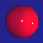 W |
 X |
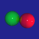 Y |
 Z |
The basics of the conversion from A-format to B-format is to perform a proper matrixing of the signals coming from the capsules.
In the case of a Soundfield / Core Sound microphone (type I A-format), the matrixing formulas are:
W' = FLU+FRD+BLD+BRU
X' = FLU+FRD-BLD-BRU
Y' = FLU-FRD+BLD-BRU
Z' = FLU-FRD-BLD+BRU
In the case of a DPA-4 microphone (type II A-format), instead, the formulas are:
W' = FLD+FRU+BLU+BRD
X' = FLD+FRU-BLU-BRD
Y' = FLD-FRU+BLU-BRD
Z' = -FLD+FRU+BLU-BRD
The signals obtained by matrixing are denoted with an apex ' - this is because these are not yet the required output signals, some further filtering si required. A complex mathematical theory is required for computing the proper filters to be applied. This theory produces two filters, one to be applied to W' (Fw, for producing W), and another filter FXYZ to be applied to any of X', Y' and Z', for producing the corresponding channel X, Y and Z. These filters perform some substantial gain equalization, but also phase is affected.
My mathematical skillness in not good enough for understanding how the equations of these filters have been derived. The skilled reader is redirected to the relevant papers (and patent) by Michael Gerzon and Peter Craven (the inventors of the Soundfield microphone) for more information. Click here for the Wikipedia entry, with links to the papers/patent cited above. I report here just the result, expressed as complex frequency response of these 2 filters:


In which:
r = distance of each capsule from the center of the tetrahedron in m
w = angular frequency in rad/s (w = 2pf)
c = speed of sound in m/s (assumed here equal to 340 m/s)
The following charts show the frequency response (magnitude & phase) of the above two theoretical filters:
But nowadays, the power of modern computers releases us form the need to perform advanced math computations: we can solve the problem numerically, starting from anechoic measurements performed on the real microphone. This approach has the advantage that the numerical filters will also correct for any minor deviations of the microphones from the theoretical response, so that their frequency response and phase response will be perfect (at least for the directions along which the measurements have been performed).
These measurements can be carried out also without the availability of an anechoic room, as modern impulse response measurement techniques are now available, allowing us to easily "window out" unwanted room reflections. You need just to have a room big enough, so that the reflections arrive with a substantial delay after the direct sound (you can also work outdoor, if the weather is good and there is no wind).
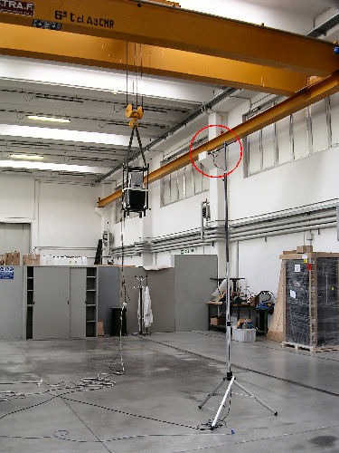
The following pictures describe the scheme of such a measurement setup, and a photo showing it in practice. The microphones are evidenced by means of a surrounding red circle.
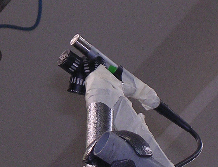
In practice, two sets of measurements are done. In the first set, each of the 4 capsules is compared side-by-side with a reference measurement microphone, as shown in the following picture:
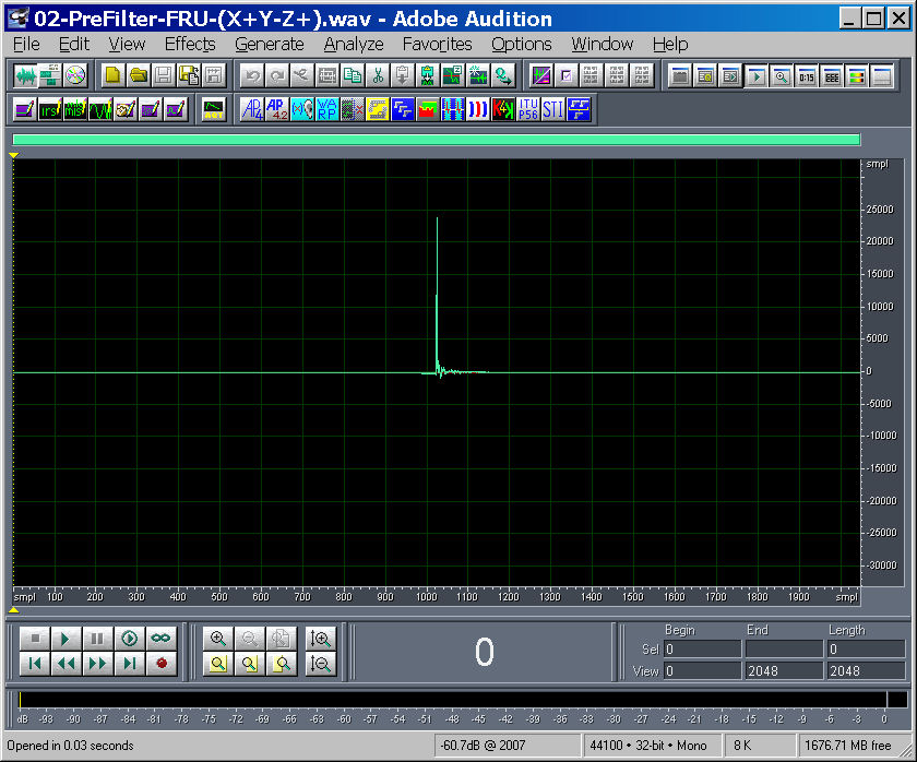
The results of such a measurment is a stereo IR, containing the response of the capusle-under-test in the left channel, and the response of the reference microphone in the right channel, as shown in the following picture:
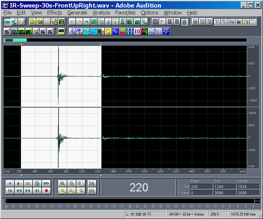
Of course, only the highlighted portion is processed, excluding the ground reflection (the impulse arriving just at the right of the selection)
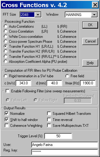
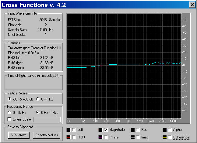
The transfer function between the capsule-under-test and the reference microphone is computed, and employed as a per-capsule equalizing filter. This ensures that all 4 capsules are perfectly identical, producing flat frequency response and linear phase response. The following picture demonstrates the usage of the Aurora plugin named Cross Functions for perfoming the computation of the transfer function:
The plugin can save the result as a time-domain waveform (an impulse response, in practice):
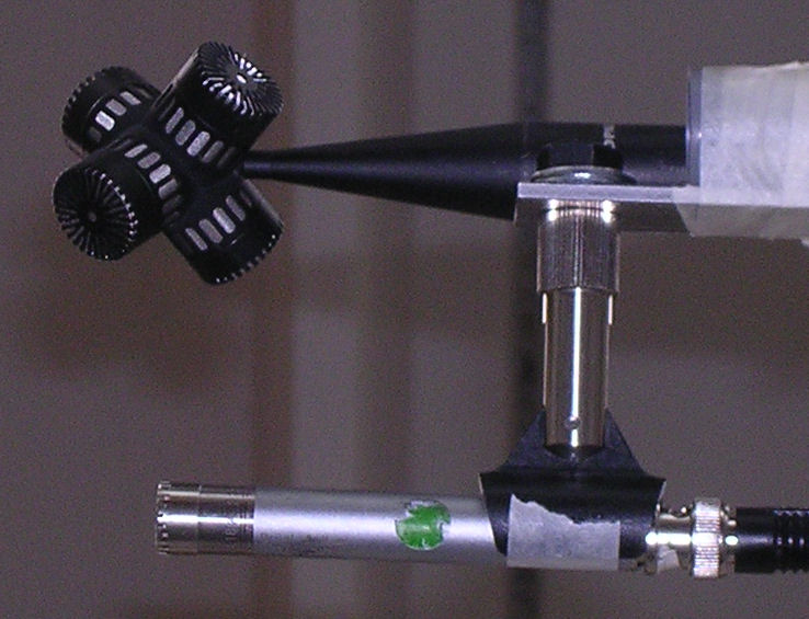
A second set of measurements is made processing the signals of the capsules through their equalizing pre-filters, and matrixing the resulting filtered signals with the formulas shown above. The results are of course W', X', Y' and Z'. The measurement is repeated three times, aligning the probe with the source along the three cartesian axes, so that for each of the three channels X, Y and Z it is possible to get an impulse response which should, in principle, equate that of the reference microphone. The following picture shows this second type of measurements (for Z).
This way, it is possible to measure the transfer function between each of the 4 processed signals (W', X', Y' and Z') and the reference microphone. These transfer functions are treated as the post-filters, performing the required equalization and conversion to the "correct" signals W, X, Y and Z.
Please notice that the post-filter for the W channel is scaled down by 3 dB (the coefficients are multplied by 0.707), so that the resulting W channel will be gain-reduced, as the standard B-format signal is expected to be.
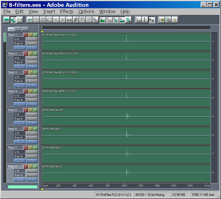
At the end, we have 8 numerical filters, which are in the form of FIR filters (impulse responses) of suitable lenght, typically between 2048 and 8192 samples (depending on the low.-frequency limit of the analysis and on the sampling rate). These are shown here (the first 4 are the pre-filters, one for each capsule, and the last 4 are the post filters):
It can be interesting to show here the frequency response (magnitude & phase) of the 4 post-filters, which theoretically should be very close to the theoretical ones, which have been described previously:
It can be seen how these frequency responses are quite different from the theoretical ones...
These 8 filters (4 pre-filters, each per capsule, and 4 post-filters, each per output channel) should be used as follows:
For performing this filtering/matrixing/filtering in real time, while recording with an A-format microphone, a fast multichannel convolver is needed. Now a freeware solution does exists, the Convolver-VST open-source program. This plugin can be loaded with an 8-channels WAV file, containing the 8 filters obtained from the measurements.
Of course, after having performed the first 4 pre-filters, the signals must be matrixed before being passed through the second group of 4 post-filters.
AudioMulch or Plogue Bidule can be used as host programs. In the example shown here, AudioMulch was employed.
The problem with Audiomulch is that its 4x4 matrix does not allow for specifying polarity-inversion. If the 4x4 matrix module had been capable of this, it would be possible to employ the following processing scheme (called "contraption" in AudioMulch):
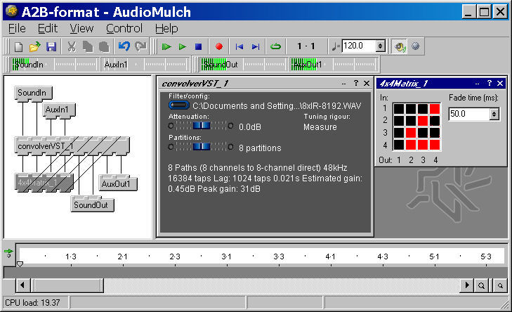
Which is quite simple to understand. In the matrix, black square means positive signal and red square means polarity-reversed (negative signal).
This will be hopefully implemented in the next revision of Audiomulch.
In the meanwhile, as the current matrixes in Audiomulch only allow to specify positive signals, it is necessary to create "externally" polarity-reversed signals, and employing half of an 8x8 matrix for performing the required processing, as shown in the following picture:

In this case, the inputs n. 5..8 of the matrix are fed with inverted (polarity-reversed) versions of the 4 signals coming out from the first 4 channels of Convolver-VST (performing the convolution with pre-filters).
After matrixing, the 4 signals are sent back to the Convolver-VST plugin (inputs n. 5..8), which applies the post-filters and outputs the wanted WXYZ signals.
The CPU load shown on the above pictures is around 19%. This was benchmarked on a laptop computer featuring a Pentium-M 740 processor (1.73 GHz). This leaves enough CPU power for performing other tasks, such as monitoring the signals by means of Visual Virtual Microphone, saving the B.format stream to disk, etc...
All the files required for performing the processing (Audiomulch AMH file containing the patchwork, the 8 FIR filters for my DPA-4 microphone, and the Excel spreadheet employed for plotting the frequency responses of theoretical and experimental post-filters) can be downloaded from this directory.
For more information about measurement technique and computation of the inverse filters for your own A-format microphone, you can contact Angelo Farina.
Notice: the Soundfield technology was patented by Gerzon and Craven (US patent n.4,042,779) in 1974-75, but this patent is now expired. So the technology described here can be freely employed by everyone. The numerical approach for performing the required filtering, based on impulse response measurements on the actual microphone, is substantially new. However, as this web page, published in Italy, is considered equivalent to a written publication, this web page makes it impossible for everyone to file a patent, claiming exclusive rights on this approach. The author of this web page wants that this technology remains free for everyone. The date of first publication of this web page is 18 October 2006.